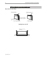
STEPS:
1. Prepare the four screw clamps for the HMI5056/5070/5080 or the six screw clamps for the
HMI5104/5121/5150 by positioning the metal brackets at the midpoints of the screws. Position the screws
so that the ends don’t protrude from the plastic portions.
2. Set the OIT in the panel cutout and hold it in place until all clamps are in position.
3. Tighten the screw clamps until all are uniformly snug.
CAUTION: Do not over-tighten the screws beyond snugness, or you may damage the housing.
REINSTALLATION: Because the gasket will take a “set” to the panel, be sure to reinstall the OIT to the same
panel cutout when a NEMA 4 seal is required. For best results, also replace the gasket itself.
Con fig u ra tion Wir ing
The OIT must be configured for a particular protocol before use. The
EZware-5000
software (used on a PC with
Windows XP, 2000 or Vista) is used for configuring the OIT. For detailed instructions on installing and using the
software, please refer to the software documentation section of this manual.
Con nect the OIT to the PC for Con fig u ra tion
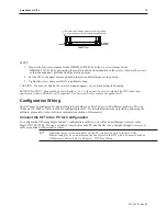
To configure the OIT using Maple System’s configuration software, you will need an Ethernet crossover cable,
Maple P/N 7431-0102. If using a switch or router between the PC and the OIT, use a straight-through or crossover
cable as required by the switch or router.
If an Ethernet port is not available on the PC, you may be able to install a USB
Ethernet adapter. You can also transfer the project to the OIT with a Compact Flash or
USB memory device. Refer to Chapter 2, OIT Local Setup.
1010-1007, Rev 05
In stal la tion of OITs
15
Position screw clamps 6 places in slots provided:
2 screw clamps each side and one top and bottom
Panel
Side View
Summary of Contents for Silver Plus Series
Page 20: ...1010 1007 Rev 05 16 Silver Plus Series Installation Operation Manual ...
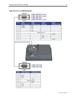
Page 31: ...COM Ports for the HMI5056 5070 1010 1007 Rev 05 Connect the OIT to the PLC or Controller 27 ...
Page 38: ...1010 1007 Rev 05 34 Silver Plus Series Installation Operation Manual ...
Page 49: ...7 Click the Shape tab 1010 1007 Rev 05 Creating Your First Project 45 ...
Page 62: ...1010 1007 Rev 05 58 Silver Plus Series Installation Operation Manual ...
Page 75: ...3 Click OK The System Parameter Settings dialog appears 1010 1007 Rev 05 Using EZware 5000 71 ...
Page 132: ...1010 1007 Rev 05 128 Silver Plus Series Installation Operation Manual ...
Page 156: ...1010 1007 Rev 05 152 Silver Plus Series Installation Operation Manual ...
Page 210: ...1010 1007 Rev 05 206 Silver Plus Series Installation Operation Manual ...
Page 216: ...1010 1007 Rev 05 212 Silver Plus Series Installation Operation Manual ...
Page 246: ...1010 1007 Rev 05 242 Silver Plus Series Installation Operation Manual ...

