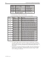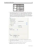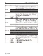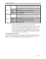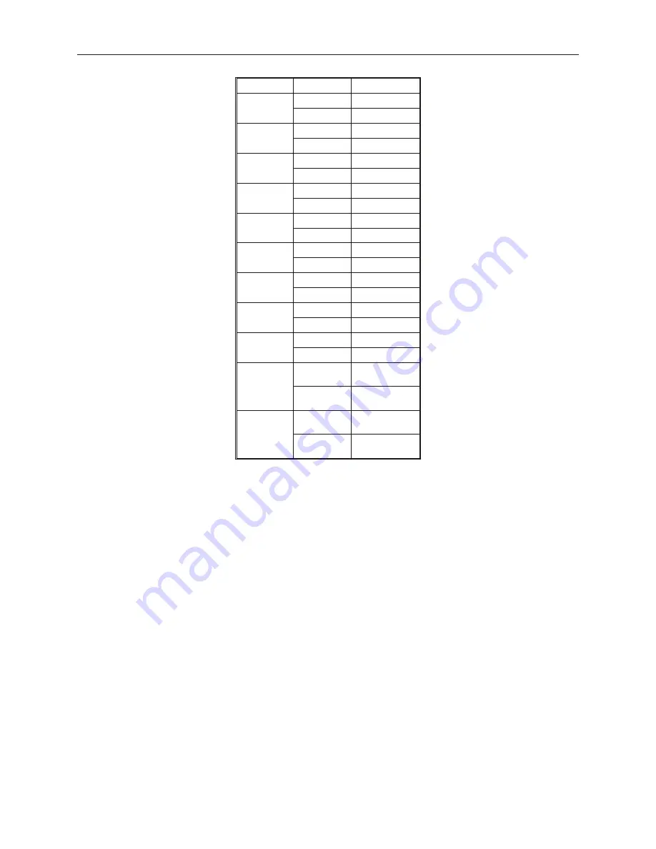
Format
Options
Range
16-bit BCD
Low Limit
0
High Limit
65,535
32-bit BCD
Low Limit
0
High Limit
4,294,967,295
16-bit Hex
Low Limit
0
High Limit
65,535
32-bit Hex
Low Limit
0
High Limit
4,294,967,295
16-bit
Binary
Low Limit
0
High Limit
65,535
32-bit
Binary
Low Limit
0
High Limit
4,294,967,295
16-bit
Unsigned
Low Limit
0
High Limit
65535
16-bit
Signed
Low Limit
-32,768
High Limit
32,768
32-bit
Unsigned
Low Limit
0
High Limit
4,294,967,295
32-bit
Signed
Low Limit
-2,147,483,64
7
High Limit
+2,147,483,64
7
32-bit Float
Low Limit
-9999999999.
9999999999
High Limit
+9999999999.
9999999999
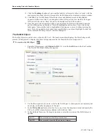
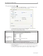
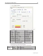
10. Click the
Font
tab to configure the font.
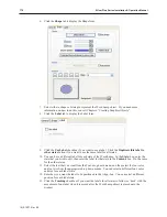
11. Select your
Font
from the drop down menu. Enter the
color
that you want for the digits
displayed in the color: box and then select the
font size.
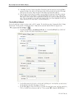
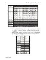
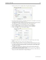
12. Enter how you want the digits to be positioned in the Align: box. The choices are:
•
Right Adjust
- aligns the number to the right margin of the part.
•
Left Adjust
- aligns the number to the left margin of the part.
•
Leading Zero
- inserts leading zeroes
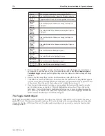
13. Click
OK
. The Numeric Data Object form closes and the main screen of EasyBuilder appears
with the cursor tied to a rectangular outline of the part you just created at the upper left corner
of the screen. Move the part to the desired location on the window.
14. Once the part is placed onto the window, you can modify the attributes by double-clicking on
the part to display the Numeric Data Object’s Attribute dialog box.
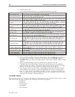
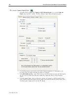
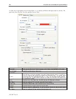
The Nu meric In put Ob ject
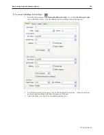
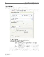
The Numeric Input Object is used to read and write numeric values to a PLC register. The object continuously reads
the PLC register and displays the corresponding value in the format specified. The PLC register can be a 16-bit or
32-bit word. By using the keypad, the operator can enter a new value.
1010-1007, Rev 05
Rep re senting Data with Graph ics Ob jects
187
Summary of Contents for Silver Plus Series
Page 20: ...1010 1007 Rev 05 16 Silver Plus Series Installation Operation Manual ...
Page 31: ...COM Ports for the HMI5056 5070 1010 1007 Rev 05 Connect the OIT to the PLC or Controller 27 ...
Page 38: ...1010 1007 Rev 05 34 Silver Plus Series Installation Operation Manual ...
Page 49: ...7 Click the Shape tab 1010 1007 Rev 05 Creating Your First Project 45 ...
Page 62: ...1010 1007 Rev 05 58 Silver Plus Series Installation Operation Manual ...
Page 75: ...3 Click OK The System Parameter Settings dialog appears 1010 1007 Rev 05 Using EZware 5000 71 ...
Page 132: ...1010 1007 Rev 05 128 Silver Plus Series Installation Operation Manual ...
Page 156: ...1010 1007 Rev 05 152 Silver Plus Series Installation Operation Manual ...
Page 210: ...1010 1007 Rev 05 206 Silver Plus Series Installation Operation Manual ...
Page 216: ...1010 1007 Rev 05 212 Silver Plus Series Installation Operation Manual ...
Page 246: ...1010 1007 Rev 05 242 Silver Plus Series Installation Operation Manual ...

