3.
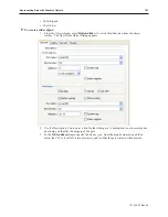
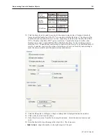
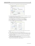
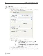
In the Read address frame, select the
device type
from the drop down menu and then specify
the
PLC register address
that the part continuously reads. Select
No. of words:
Remember, 1
word = 2 characters.
4.
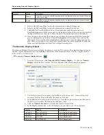
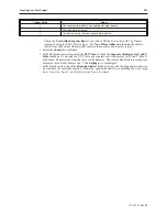
In the Notification frame, check the
Enable
box if the OIT is to notify the PLC when the
object has been activated. Configure whether the specified bit is to be turned on or off,
whether the bit is to be written before or after the data is written, and finally specify the PLC
Coil that the OIT is to write to.
5.
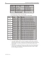
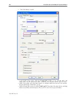
In the Keyboard section, select your
kepyad
from the drop-down menu, and then select the
popup position
relative to the OIT screen using the nine-dot matrix indicated (for instance,
clicking the middle dot will pop the keypad up in the middle of the display).
6.
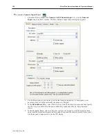
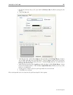
Click the
Security
tab to display the security form.
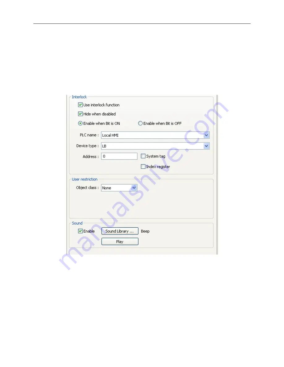
7.
To enable security for the object, click the
Enable
checkbox and configure PLC settings from
the drop-down menu.
8.
Select the
level of user restriction
from the Object class drop-down menu.
9.
You may select to make the object invisible while protected. You may also wish to enable a
sound that plays when the protection keypad popus up. Sounds can be selected from sound
libraries.
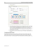
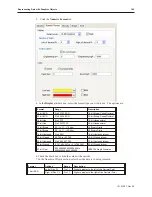
10. Click the
Shape
tab to configure a shape or bitmap that is displayed behind the number.
11. Click the
Font
tab to configure the font.
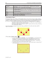
The Moving Shape Ob ject
The Moving Shape Object performs three functions depending upon the values in three consecutive PLC registers:
• Similar to the Word Lamp Object, the Moving Shape object continuously reads a PLC register and
displays the corresponding shape or bitmap that is tagged to the number of states defined.
1010-1007, Rev 05
194
Sil ver Plus Se ries In stal la tion & Op er a tion Man ual
Summary of Contents for Silver Plus Series
Page 20: ...1010 1007 Rev 05 16 Silver Plus Series Installation Operation Manual ...
Page 31: ...COM Ports for the HMI5056 5070 1010 1007 Rev 05 Connect the OIT to the PLC or Controller 27 ...
Page 38: ...1010 1007 Rev 05 34 Silver Plus Series Installation Operation Manual ...
Page 49: ...7 Click the Shape tab 1010 1007 Rev 05 Creating Your First Project 45 ...
Page 62: ...1010 1007 Rev 05 58 Silver Plus Series Installation Operation Manual ...
Page 75: ...3 Click OK The System Parameter Settings dialog appears 1010 1007 Rev 05 Using EZware 5000 71 ...
Page 132: ...1010 1007 Rev 05 128 Silver Plus Series Installation Operation Manual ...
Page 156: ...1010 1007 Rev 05 152 Silver Plus Series Installation Operation Manual ...
Page 210: ...1010 1007 Rev 05 206 Silver Plus Series Installation Operation Manual ...
Page 216: ...1010 1007 Rev 05 212 Silver Plus Series Installation Operation Manual ...
Page 246: ...1010 1007 Rev 05 242 Silver Plus Series Installation Operation Manual ...

