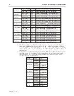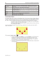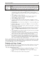
Style
Option
Description
X axis only
Reads two 16-bit registers. Register #1 determines the state of the shape displayed.
Register #2 determines the position of the shape along the X axis. The OIT places the
shape relative to the starting location. For example, if the shape is located on the
window at X=50, and Register #2 has a value of 10, the shape is placed at X=60. If
Register #2 has a value of -10, the shape is placed at X=40.
No. of states:
Range = 0 to 255
Input low:
Not used
Input high:
Not used
Y axis only
Reads two 16-bit registers. Register #1 determines the state of the shape displayed.
Register #2 determines the position of the shape along the Y axis. The OIT places the
shape relative to the starting location. For example, if the shape is located on the
window at Y=50, and Register #2 has a value of 10, the shape is placed at Y=60. If
Register #2 has a value of -10, the shape is placed at Y=40.
No. of states:
Range = 0 to 255
Input low:
Not used
Input high:
Not used
X & Y axis
Reads three 16-bit registers. Register #1 determines the state of the shape displayed.
Register #2 determines the position of the shape along the X axis. Register #3
determines the position of the shape along the Y axis. The OIT places the shape
relative to the starting location. For example, if the shape is located on the window at
X=50, Y=10, and Register #2 has a value of 10 and Register #3 has a value of 5, the
shape is placed at X=60, Y=15. If Register #2= -10 and Register #3= -5, the shape is
placed at X=40, Y=5.
No. of states:
Range = 0 to 255
Input low:
Not used
Input high:
Not used
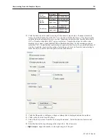
X axis w/scaling
Reads two 16-bit registers. Register #1 determines the state of the shape displayed.
Register #2 determines the position of the shape along the X axis. The OIT places the
shape relative to the starting location using scaling to calculate position. For example, if
Input low=0, Input high=10, Scaling low=0, and Scaling high=100, then when the value
in the PLC register increases by 1, the shape moves
right
along the X axis by 10 pixels.
No. of states:
Range = 0 to 255
Input low:
This is the lowest raw data value that is in the PLC data register
Input high:
This is the highest raw data value that is in the PLC data register
Scaling low:
This is the low scaled value.
Scaling high:
This is the high scaled value.
Y axis w/scaling
Reads two 16-bit registers. Register #1 determines the state of the shape displayed.
Register #2 determines the position of the shape along the Y axis. The OIT places the
shape relative to the starting location using scaling to calculate position. For example, if
Input low=0, Input high=10, Scaling low=0, and Scaling high=100, then when the value
in the PLC register increases by 1, the shape moves
down
along the Y axis by 10 pixels.
No. of states:
Range = 0 to 255
Input low:
This is the lowest raw data value that is in the PLC data register
Input high:
This is the highest raw data value that is in the PLC data register
Scaling low:
This is the low scaled value.
Scaling high:
This is the high scaled value.
1010-1007, Rev 05
196
Sil ver Plus Se ries In stal la tion & Op er a tion Man ual
Summary of Contents for Silver Plus Series
Page 20: ...1010 1007 Rev 05 16 Silver Plus Series Installation Operation Manual ...
Page 31: ...COM Ports for the HMI5056 5070 1010 1007 Rev 05 Connect the OIT to the PLC or Controller 27 ...
Page 38: ...1010 1007 Rev 05 34 Silver Plus Series Installation Operation Manual ...
Page 49: ...7 Click the Shape tab 1010 1007 Rev 05 Creating Your First Project 45 ...
Page 62: ...1010 1007 Rev 05 58 Silver Plus Series Installation Operation Manual ...
Page 75: ...3 Click OK The System Parameter Settings dialog appears 1010 1007 Rev 05 Using EZware 5000 71 ...
Page 132: ...1010 1007 Rev 05 128 Silver Plus Series Installation Operation Manual ...
Page 156: ...1010 1007 Rev 05 152 Silver Plus Series Installation Operation Manual ...
Page 210: ...1010 1007 Rev 05 206 Silver Plus Series Installation Operation Manual ...
Page 216: ...1010 1007 Rev 05 212 Silver Plus Series Installation Operation Manual ...
Page 246: ...1010 1007 Rev 05 242 Silver Plus Series Installation Operation Manual ...

