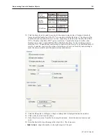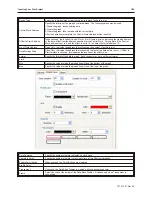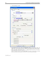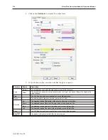
• If you'd like reference lines on the plot, check the
Reference line
checkboxes and specify the
position.
4.
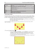
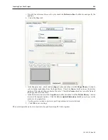
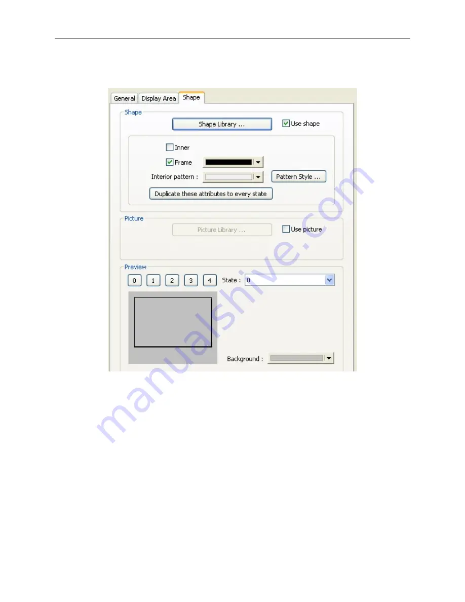
Select the Shape tab:
•
•
• In the Shape section, , check the
Use shape
checkbox and then click the
Shape library...
button to
select a background shape from the shape library. Check the
Inner
checkbox to use the interior
portion of the selected shape and select the color. Check the
Frame
checkbox to use the frame of
the shape and select the color.
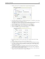
• In the Picture section, select the
Use picture
checkbox and then click the
Picture library...
button
to select a background picture. Click the
Set to original dimensions
checkbox to always set the
picture to its original size.
• Use the preview section to preview a part's appearance in its selected state.
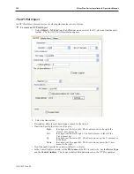
5. Click
OK
to save settings.
The next chapter shows how to construct a keypad for editing PLC data registers.
1010-1007, Rev 05
Cre ating Your First Project
205
Summary of Contents for Silver Plus Series
Page 20: ...1010 1007 Rev 05 16 Silver Plus Series Installation Operation Manual ...
Page 31: ...COM Ports for the HMI5056 5070 1010 1007 Rev 05 Connect the OIT to the PLC or Controller 27 ...
Page 38: ...1010 1007 Rev 05 34 Silver Plus Series Installation Operation Manual ...
Page 49: ...7 Click the Shape tab 1010 1007 Rev 05 Creating Your First Project 45 ...
Page 62: ...1010 1007 Rev 05 58 Silver Plus Series Installation Operation Manual ...
Page 75: ...3 Click OK The System Parameter Settings dialog appears 1010 1007 Rev 05 Using EZware 5000 71 ...
Page 132: ...1010 1007 Rev 05 128 Silver Plus Series Installation Operation Manual ...
Page 156: ...1010 1007 Rev 05 152 Silver Plus Series Installation Operation Manual ...
Page 210: ...1010 1007 Rev 05 206 Silver Plus Series Installation Operation Manual ...
Page 216: ...1010 1007 Rev 05 212 Silver Plus Series Installation Operation Manual ...
Page 246: ...1010 1007 Rev 05 242 Silver Plus Series Installation Operation Manual ...

