Chapter 2 - OIT Local Setup
Factory Configuration
Each OIT arrives from the factory with a demo project file that illustrates some of the most popular features of the
OIT. Please follow the directions enclosed in
Chapter 4, Creating Your First Project
, to configure your OIT for the
PLC that you are using.
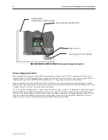
The OIT also has a black reset push button and a four position DIP switch located through an access hole on the
back of the enclosure. The reset switch can be used to reinitialize the OIT if the OIT malfunctions. Only Dip
switch 1 has functionality. Dip switch 1 puts the OIT into Touch Calibration mode. For normal operation, all of
the DIP switches should be set to the OFF position.
This chapter describes how to use the Silver Plus Series’ local setup options. The local setup allows touchscreen
calibration, transferring projects to and from the OIT, configuring the OIT’s IP settings, passwords, time and date,
screen contrast, as well as managing the storage of recipe and history files. Additionally, memory and other system
information can be viewed.
Calibrating the Touchscreen
The touchscreen of the OIT is fully calibrated before it leaves the factory so you shouldn’t need to adjust it.
However, with time the touchscreen may need to be recalibrated.
4
To calibrate the touchscreen:
1. Turn Dip Switch 1 ON.
2. Cycle power to the OIT.
3. After the OIT displays a crosshair cursor, you are prompted to touch the cursor for:
a. Top left position
b. Top right position
c. Bottom right position
d. Bottom left position
e. Center position.
4. The OIT will then resume initializing.
Getting into Local Setup
Accessing the local setup menus requires a USB-mouse be connected to the OIT. Using the mouse, point to the
lower right-hand corner of the OIT. The open bar icon will appear.
Click on the icon to call up the setup toolbar:
1010-1007, Rev 05
OIT Lo cal Setup
17
Open/close bar
icon
Virtual keyboard
icon
System settings
icon
System info icon
Small keyboard
icon
Large keyboard
icon
Summary of Contents for Silver Plus Series
Page 20: ...1010 1007 Rev 05 16 Silver Plus Series Installation Operation Manual ...
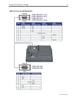
Page 31: ...COM Ports for the HMI5056 5070 1010 1007 Rev 05 Connect the OIT to the PLC or Controller 27 ...
Page 38: ...1010 1007 Rev 05 34 Silver Plus Series Installation Operation Manual ...
Page 49: ...7 Click the Shape tab 1010 1007 Rev 05 Creating Your First Project 45 ...
Page 62: ...1010 1007 Rev 05 58 Silver Plus Series Installation Operation Manual ...
Page 75: ...3 Click OK The System Parameter Settings dialog appears 1010 1007 Rev 05 Using EZware 5000 71 ...
Page 132: ...1010 1007 Rev 05 128 Silver Plus Series Installation Operation Manual ...
Page 156: ...1010 1007 Rev 05 152 Silver Plus Series Installation Operation Manual ...
Page 210: ...1010 1007 Rev 05 206 Silver Plus Series Installation Operation Manual ...
Page 216: ...1010 1007 Rev 05 212 Silver Plus Series Installation Operation Manual ...
Page 246: ...1010 1007 Rev 05 242 Silver Plus Series Installation Operation Manual ...


