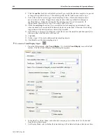
5.
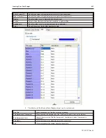
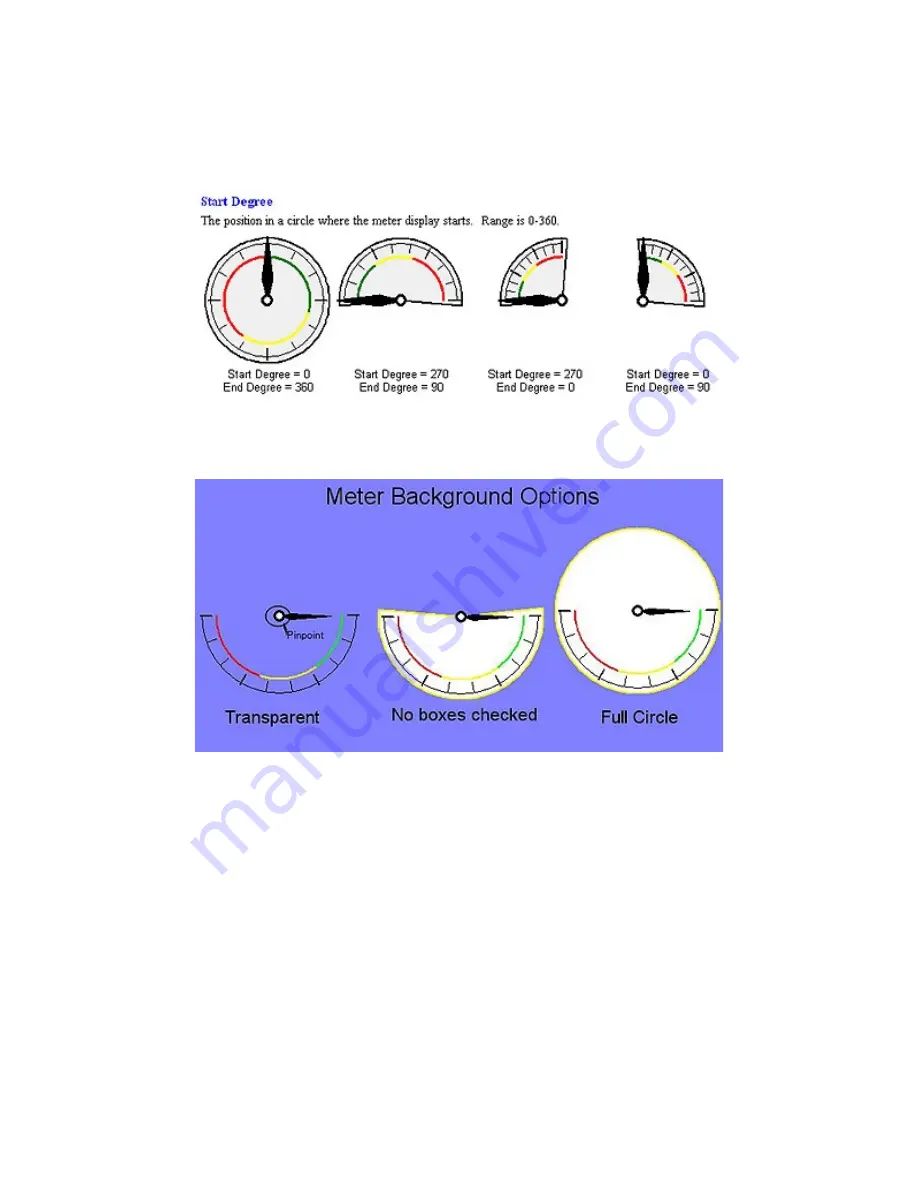
In the Degree section, you can select the range of your meter, where the range is 0 to 360.
The start degree, 0 is at 12:00. Below are four examples of start and end degrees for different
meters:
Note that meters can have any start and end degree between 0 and 360.
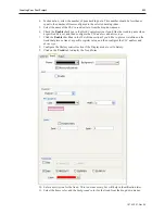
6.
The Background section allows you to select background options for the meter. The
following illustrations illustrates how your meter will appear with different options checked:
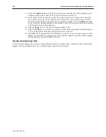
7.
The Tick Marks section allows you to configure the length, scale and sub-scale of the tick
marks.
8.
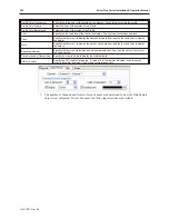
In the Pointer section, select
arm style
,
color
,
length
, and
width
.
9.
The Pinpoint section allows you to adjust the style and size of the pinpoint. See the
illustration above to see the pinpoint.
1010-1007, Rev 05
Bar Graphs, Me ters and Trends
217
Summary of Contents for Silver Plus Series
Page 20: ...1010 1007 Rev 05 16 Silver Plus Series Installation Operation Manual ...
Page 31: ...COM Ports for the HMI5056 5070 1010 1007 Rev 05 Connect the OIT to the PLC or Controller 27 ...
Page 38: ...1010 1007 Rev 05 34 Silver Plus Series Installation Operation Manual ...
Page 49: ...7 Click the Shape tab 1010 1007 Rev 05 Creating Your First Project 45 ...
Page 62: ...1010 1007 Rev 05 58 Silver Plus Series Installation Operation Manual ...
Page 75: ...3 Click OK The System Parameter Settings dialog appears 1010 1007 Rev 05 Using EZware 5000 71 ...
Page 132: ...1010 1007 Rev 05 128 Silver Plus Series Installation Operation Manual ...
Page 156: ...1010 1007 Rev 05 152 Silver Plus Series Installation Operation Manual ...
Page 210: ...1010 1007 Rev 05 206 Silver Plus Series Installation Operation Manual ...
Page 216: ...1010 1007 Rev 05 212 Silver Plus Series Installation Operation Manual ...
Page 246: ...1010 1007 Rev 05 242 Silver Plus Series Installation Operation Manual ...

