2.
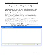
Click the
New...
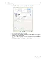
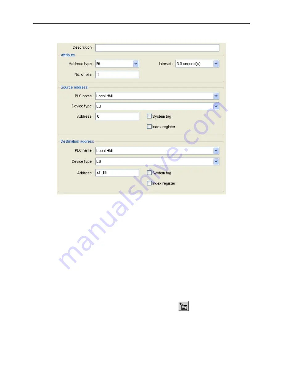
button. The Data Transfer (Time-based)Object dialog box appears.
3.
Use the Description: box to enter a
title
for the Data Transfer part. A description is not
necessary but does help you identify the purpose of the part.
4.
In the Attribute box, configure the Address type to transfer whether by bit or word, the
interval of transfer and the number of bits or words to transfer.
5.
In the Source address frame, select the
PLC name
and
device type
from their drop down
menus and then configure the
address
.
6.
In the
Destination address
frame, select the PLC coils or registers that receive the data.
7.
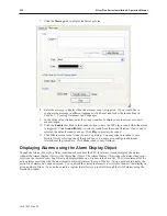
Click
OK
to close the Data Transfer Object dialog. The Data Transfer Object dialog box
reappears with the new entry listed. You can edit the attributes of an existing Data Transfer
object by clicking on the
Settings...
button. Any entries can be deleted by clicking on the
Delete
button.
8.
Click
Exit
to close the Data Transfer Object dialog box. The Data Transfer Object is active
no matter what windows are currently displayed on the OIT screen; therefore, you do not
have to place the object onto a window screen.
Using the Rec ipe Trans fer (Data Trans fer, Trig ger Based) Ob ject
The Data Transfer, Trigger-Based (Recipe Transfer) Object is used to download or save data from one or more PLC
registers to the OIT’s internal registers that are reserved for recipes. This occurs when the object is activated by a
press from the OIT operator. Each Object created can transfer from 1-32767 continuous registers.
4
To create a Recipe Transfer (Data Transfer, Trigger Based) Object
1.
From the Objects menu, click
Data Transfer (Trigger-based).
Or click the
Data Transfer
1010-1007, Rev 05
238
Sil ver Plus Se ries In stal la tion & Op er a tion Man ual
Summary of Contents for Silver Plus Series
Page 20: ...1010 1007 Rev 05 16 Silver Plus Series Installation Operation Manual ...
Page 31: ...COM Ports for the HMI5056 5070 1010 1007 Rev 05 Connect the OIT to the PLC or Controller 27 ...
Page 38: ...1010 1007 Rev 05 34 Silver Plus Series Installation Operation Manual ...
Page 49: ...7 Click the Shape tab 1010 1007 Rev 05 Creating Your First Project 45 ...
Page 62: ...1010 1007 Rev 05 58 Silver Plus Series Installation Operation Manual ...
Page 75: ...3 Click OK The System Parameter Settings dialog appears 1010 1007 Rev 05 Using EZware 5000 71 ...
Page 132: ...1010 1007 Rev 05 128 Silver Plus Series Installation Operation Manual ...
Page 156: ...1010 1007 Rev 05 152 Silver Plus Series Installation Operation Manual ...
Page 210: ...1010 1007 Rev 05 206 Silver Plus Series Installation Operation Manual ...
Page 216: ...1010 1007 Rev 05 212 Silver Plus Series Installation Operation Manual ...
Page 246: ...1010 1007 Rev 05 242 Silver Plus Series Installation Operation Manual ...

