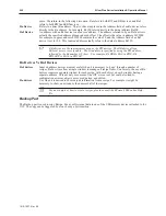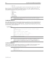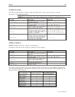
same. Therefore, in the following discussion, R
n
refers to both RW and RB devices, and R
n
I
refers to both RWI and RBI devices.
R
n
Device
Refers to a direct R
n
address. That is, the value placed in the Address field of an R
n
device refers
directly to the R
n
address. For example, R
n
100 refers directly to the data at address R
n
100.
R
n
I Device
An address with an R
n
I device is an
Indexed
address. The address referred to by an R
n
I device is
actually the specified address plus an indexed offset. The offset is the value in address LW9000.
For example, suppose address LW9000 contains the value 50, and the Address field of an R
n
I
device is set to 100. This
Indexed
address actually refers to the data at address R
n
150.
RB devices use the same memory area as the RW devices. The RB device allows
Bit-level access to recipe data. The bit address is specified by using the RW address,
followed by the bit number 0-F (hex). For example, Bit RB0 is Bit 0 in RW0; Bit
RW2047F is Bit 16 in RW2047.
Rn De vices Vs RnI De vices
R
n
I devices
Indexed address devices are most useful when it is necessary to ‘page’ through a number of
recipes. R
n
I devices allow a single window to manage all recipe items. Conversely, the use of R
n
devices requires a separate window for each recipe, with each object on each window having a
separate address. This not only uses more of the OIT’s resources, but could also lead to
configuration errors as objects are copied, pasted, and edited.
R
n
devices
Use when it is desired to show unique information from a recipe. For example, it might be
necessary to show, one window, the names of all of the recipes.
4
For an example of how to create recipes, please consult the EZware-5000 online Help
file.
Backup Part
The Backup part is used to copy Recipe, Event, or Historical data to one of the USB memory devices attached to the
OIT. The copy can be triggered by a touch or by a bit transition.
1010-1007, Rev 05
240
Sil ver Plus Se ries In stal la tion & Op er a tion Man ual
Summary of Contents for Silver Plus Series
Page 20: ...1010 1007 Rev 05 16 Silver Plus Series Installation Operation Manual ...
Page 31: ...COM Ports for the HMI5056 5070 1010 1007 Rev 05 Connect the OIT to the PLC or Controller 27 ...
Page 38: ...1010 1007 Rev 05 34 Silver Plus Series Installation Operation Manual ...
Page 49: ...7 Click the Shape tab 1010 1007 Rev 05 Creating Your First Project 45 ...
Page 62: ...1010 1007 Rev 05 58 Silver Plus Series Installation Operation Manual ...
Page 75: ...3 Click OK The System Parameter Settings dialog appears 1010 1007 Rev 05 Using EZware 5000 71 ...
Page 132: ...1010 1007 Rev 05 128 Silver Plus Series Installation Operation Manual ...
Page 156: ...1010 1007 Rev 05 152 Silver Plus Series Installation Operation Manual ...
Page 210: ...1010 1007 Rev 05 206 Silver Plus Series Installation Operation Manual ...
Page 216: ...1010 1007 Rev 05 212 Silver Plus Series Installation Operation Manual ...
Page 246: ...1010 1007 Rev 05 242 Silver Plus Series Installation Operation Manual ...

