Chapter 3 - Con nect the OIT to the PLC or Controller
The Silver Plus Series family of OITs can connect to one, two or more PLC/controllers. This is accomplished via
two 9-pin D-sub serial communications connectors (Port A and Port B) and one Ethernet port. Each PLC/Controller
has its own wiring requirements. Maple Systems offers OIT-to-PLC/Controller communication cables that connect
directly to software controlled COM1, which is available on either Port A or Port B for most PLC/Controllers that
are built to any length and tested for high reliability. The Silver Plus Series family has three software controlled
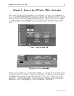
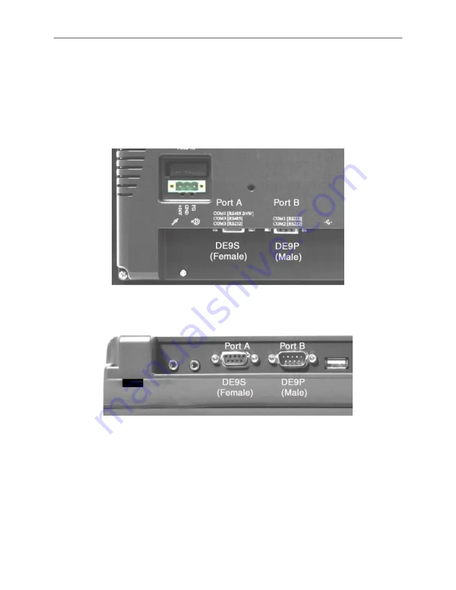
communications ports located on two physical connectors, designated as Port A and Port B (
see Figures 1 & 2,
below
).
The three software controlled ports are COM1, COM2, and COM3. Each software controlled communications port
can only be selected for one communication type. Once a communication type is selected for one of these software
controlled ports, that port cannot be used for another communication type. Each of these communication ports has
between one and three communication types. COM1 can be RS232, RS485 4-Wire, or RS485 2-Wire. COM2 is
strictly RS232. COM3 is either RS232 or RS485 2-Wire. COM1 cables are readily available for purchase from
Maple Systems. COM2 and COM3 cables are custom-made according to wiring diagrams that can be found on
Maple Systems' web site. Connecting multiple PLCs and controllers may require a splitter.
1010-1007, Rev 05
Con nect the OIT to the PLC or Controller
25
Fig ure 1 - Com Ports - Rear View
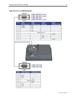
Fig ure 2 - Com Ports - Bot tom View
Summary of Contents for Silver Plus Series
Page 20: ...1010 1007 Rev 05 16 Silver Plus Series Installation Operation Manual ...
Page 31: ...COM Ports for the HMI5056 5070 1010 1007 Rev 05 Connect the OIT to the PLC or Controller 27 ...
Page 38: ...1010 1007 Rev 05 34 Silver Plus Series Installation Operation Manual ...
Page 49: ...7 Click the Shape tab 1010 1007 Rev 05 Creating Your First Project 45 ...
Page 62: ...1010 1007 Rev 05 58 Silver Plus Series Installation Operation Manual ...
Page 75: ...3 Click OK The System Parameter Settings dialog appears 1010 1007 Rev 05 Using EZware 5000 71 ...
Page 132: ...1010 1007 Rev 05 128 Silver Plus Series Installation Operation Manual ...
Page 156: ...1010 1007 Rev 05 152 Silver Plus Series Installation Operation Manual ...
Page 210: ...1010 1007 Rev 05 206 Silver Plus Series Installation Operation Manual ...
Page 216: ...1010 1007 Rev 05 212 Silver Plus Series Installation Operation Manual ...
Page 246: ...1010 1007 Rev 05 242 Silver Plus Series Installation Operation Manual ...


