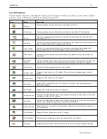
In most cases, we will describe each method when the task is first discussed. The menu method is then used whenever the
task is used in later procedures. Other conventions used in this manual are listed in the following table.
Convention
Meaning
Bold
Characters that you must type exactly as they appear. For example, if you are directed to type
a:\setup
,
you should type all the bold characters exactly as they are printed.
Italic
Placeholders for information you must provide. For example, if you are directed to type
filename
, you
should type the actual name for a file instead of the word shown in italic type. Italics are also used to
indicate a glossary term.
ALL CAPITALS
Directory names, file names, key names, and acronyms
KEY1+KEY2
A plus sign (+) between key names means to press and hold down the first key while you press the second
key.
click
Refers to clicking the primary mouse button (usually the left mouse button) once.
Double-click
Refers to quickly clicking the primary mouse button (usually the left mouse button) twice.
Right-click
Refers to clicking the secondary mouse button (usually the right mouse button) once. Right-clicking
usually opens shortcut menus.
The following table identifies symbols and margin icons.
Icon
Meaning
4
Identifies a procedure.
4
Indicates a reference to additional information.
Indicates an important note.
What You Need
The following items are needed to configure and operate your OIT.
Configuration Software
EZware -5000
Configuration Cable1
7431-0104
Personal Computer2
User Provided
Power Cable
6030-0009
24VDC Power Supply
User Provided
PLC
User Provided
Controller Information Sheet
Maple Systems provides Controller Information Sheets which contain important information specific to each
PLC.
Please locate the sheet that corresponds to your PLC on our website.
Communication Cable
(HMI to PLC)
Refer to our web site (www. maple-systems.com) for a list of available cables.
Ethernet Crossover Cable
1
Al lows you to con nect OIT directly to PC Ethernet port.
2
Computer requirements include a Pentium 1.7 GH or higher processor, 512 MB RAM, 200 MB available Hard Disk Space,
VGA or higher resolution monitor, Keyboard and Mouse, available Ethernet port, at least one RS232 port for online
simulation, Windows XP, 2000 or Vista.
OIT Ba sics
Operator Interface Terminals
(OITs) provide much more versatility than traditional mechanical control panels. An OIT
allows a plant floor operator to monitor current conditions of a control system and, if necessary, to initiate a change in the
operation of the system. OITs connect to programmable logic controllers (PLCs) typically through the PLC’s serial
communications port. The OIT can be programmed to monitor and/or change current values stored in the data memory of the
PLC.
OITs can have either text-based or graphics-based displays. A text-based OIT can display printable text characters but no
graphics. Some text-based OITs can display text characters in various sizes. A graphics-based OIT can display printable text
characters of varying fonts and sizes and graphics shapes such as icons, bitmaps, or pictures. Using pictures instead of words
or characters often greatly simplifies the operation of the OIT, making the OIT much more intuitive to use.
1010-1007, Rev 05
2
Sil ver Plus Se ries In stal la tion & Operation Man ual
Summary of Contents for Silver Plus Series
Page 20: ...1010 1007 Rev 05 16 Silver Plus Series Installation Operation Manual ...
Page 31: ...COM Ports for the HMI5056 5070 1010 1007 Rev 05 Connect the OIT to the PLC or Controller 27 ...
Page 38: ...1010 1007 Rev 05 34 Silver Plus Series Installation Operation Manual ...
Page 49: ...7 Click the Shape tab 1010 1007 Rev 05 Creating Your First Project 45 ...
Page 62: ...1010 1007 Rev 05 58 Silver Plus Series Installation Operation Manual ...
Page 75: ...3 Click OK The System Parameter Settings dialog appears 1010 1007 Rev 05 Using EZware 5000 71 ...
Page 132: ...1010 1007 Rev 05 128 Silver Plus Series Installation Operation Manual ...
Page 156: ...1010 1007 Rev 05 152 Silver Plus Series Installation Operation Manual ...
Page 210: ...1010 1007 Rev 05 206 Silver Plus Series Installation Operation Manual ...
Page 216: ...1010 1007 Rev 05 212 Silver Plus Series Installation Operation Manual ...
Page 246: ...1010 1007 Rev 05 242 Silver Plus Series Installation Operation Manual ...


