background image

4

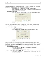
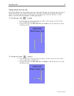
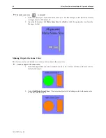
To change the state of the selected window


1.

Use the zoom pull-down menu at the top right of the screen.  

2.

The objects will appear as they would in the selected state. 

Ba sic  Ed it ing  Com mands

4

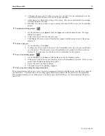
To select a graphics object 


1.

On the Edit Menu, click 

Select

 or click the mouse cursor icon in the Draw toolbar.

2.

Click on the graphics object.  For example, using Window_12, click on 

Fill Level

.  This

causes the text box to be selected, with small square blocks around the edges indicating the
boundaries of the object.  Deselect the object by clicking somewhere else in the work area.

3.

When a graphics object is selected, it can then be modified, copied, deleted, or moved to a
new location.

4

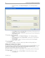
To select multiple graphics objects  

1.

On the Edit Menu, click 

Select

 or click the mouse cursor icon in the Draw toolbar.

2.

Click and hold down the left mouse button at the upper left corner of the graphics objects you
wish to highlight. For example, using Window_12, click to the left and above of  

Motor

Speed.  


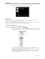
3.

Move the mouse cursor to the lower right corner of the highlighted objects.  Notice that a
rectangle is formed as you do this.  In this example, move the mouse to the right and below

Fill Level

.

4.

Release the mouse button.  The rectangle outline changes to small clear square blocks around
the perimeter of the objects selected.  Now both objects are selected.

š

If you do not completely enclose any graphics objects you wish to highlight, then they
will not be selected.

5.   Alternatively, you may select objects by holding down the CTRL key while selecting each

object until all objects are selected.

6.  When several graphics objects are selected, they can easily be moved, deleted or copied

together.

4

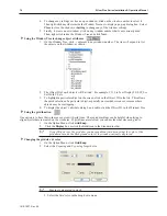
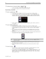
To select next object


1.

This option can be used to easily select an object that is underneath another object on the
screen.  To use this option, you must first select the overlapping object.

2.

On the Edit Menu, click 

Select Next Object

 or click on the 

Select Next Object

 icon  on the

Standard toolbar.  You can also right-click on the top-most object on the screen.  This will
display a menu with a list of the overlapping objects on the bottom.  Then  check the object
that you wish to access.

1010-1007, Rev 05

78

Sil ver  Plus  Se ries  In stal la tion  &  Op er a tion  Man ual

Summary of Contents for Silver Plus Series

Page 1: ...Installation and Operation Manual 1010 1007 Rev 05 808 134th Street SW Suite 120 Everett WA 98204 USA Phone 425 745 3229 Fax 425 745 3429 Email Web maple maple systems com www maplesystems com ...

Page 2: ... by implication or otherwise under any patent or patent rights of Maple Systems Inc Maple Systems retains the right to revise or change its products and documentation at any time without notice IF SERVICE IS REQUIRED Package the unit in its original packaging container or if unavailable any suitable rigid container If a substitute container is used surround the unit with shock absorbing material d...

Page 3: ...g Your First Project 35 Before You Begin 35 Connecting OIT to Computer 35 Starting EZware 5000 35 Creating a Sample Project 36 Setting the System Parameters 36 Creating a Popup Window 40 Creating a Startup Window 48 Finishing Up 54 Chapter 5 Simulator Mode 57 The Simulation Screen 57 Chapter 6 Using EZware 5000 59 Overview 59 The Project Manager 59 Communications Password Settings60 Editor Setting...

Page 4: ...s 209 Creating Meter Displays 211 Creating Trend Displays Data Sampling Objects 214 History Data Display Part 218 Chapter 13 Capturing Alarms and Events 223 Using Alarms 223 Monitoring Alarms with the Alarm Event Log 223 Displaying Alarms using the Alarm Display Object 225 Displaying Alarms using the Alarm Bar Object 226 Using Events 227 Monitoring Events With the Event Log Object 227 Displaying E...

Page 5: ...lus Series OITs please visit our website About Your Documentation Maple Systems provides many resources to allow you to get the most out of your Silver Plus Series OIT Silver Plus Series Operation Manual shipped with EZware 5000 as a PDF file describes installation general operation and features of the Silver Plus Series using EZware 5000 configuration software Controller Information Sheets import...

Page 6: ...4VDC Power Supply User Provided PLC User Provided Controller Information Sheet Maple Systems provides Controller Information Sheets which contain important information specific to each PLC Please locate the sheet that corresponds to your PLC on our website Communication Cable HMI to PLC Refer to our web site www maple systems com for a list of available cables Ethernet Crossover Cable 1Allows you ...

Page 7: ...A graphics object is any text icon or picture that can be displayed on the OIT Graphics objects are further defined by how they are composed or created A Text Object is a graphics object that displays text on the OIT screen A Bitmap Object is a graphics object that displays a bitmap on the OIT screen Bitmaps are files stored in the OIT to display pictures A Shape Object is a graphics object that d...

Page 8: ...t Up Down Finally a reset switch is provided on the back of the OIT to reinitialize the OIT if an operational failure occurs The Silver Plus Series is designed for industrial environments and carries a NEMA 4 rating as well as CE compliance for noise immunity and emissions There are currently EIGHT models in the Silver Plus Series Model Display size Resolution pixels LCD Type Brightness cdm2 Contr...

Page 9: ...changes state picture according to the value in a PLC data register When pressed it sends a value s to another PLC register Function Key Creates a touchscreen graphics object or runs a macro Numeric Input Displays a number stored in a PLC register The number can be changed using a numeric keypad Numeric Data Displays a number stored in a PLC register ASCII Input Displays ASCII characters stored in...

Page 10: ...graph Bar Graph Displays Creates a bar graph with alarm monitoring Meter Displays Creates a scale meter Recipe Transfer Transfers data to the specified PLC registers Event Displays Displays messages according to events that occur in the PLC Alarm Scan Contains the data for detecting alarm conditions System Message Customizes the content of system generated messages PLC Control Configures the OIT t...

Page 11: ... per Council Directive 89 336 EEC The European Union created these requirements to ensure conformity among products traded in those countries Specifically the Silver Plus Series OITs meet or exceed the noise emissions and immunity requirements as set forth in the EN50081 Emissions and EN50082 Immunity standards These products are designed to withstand electrical noise in harsh industrial environme...

Page 12: ...ctive loads or for input circuitry to the programmable logic controller Severe voltage spikes caused by these devices may damage the OIT Control Panel Design Guidelines Pay careful attention to the placement of system components and associated cable routing These items can significantly enhance the performance and integrity of your control application 1010 1007 Rev 05 8 Silver Plus Series Installa...

Page 13: ...nection to the rest of the enclosure Corrosion develops over time and prevents good electrical contract For this reason a separate wire braid should be installed from the hinged control panel to the rest of the enclosure For a more in depth overview of ground wiring techniques refer to technical note 1027 OIT Ground Wiring and Electrical Noise Reduction which you can find on our web site Connect O...

Page 14: ...n for more information A power line filter installed at the AC input to the OIT power supply is highly recommended as a safeguard against conducted RF noise which is often present on factory power lines The wires connecting the output of the power line filter to the power supply should be kept as short as possible to minimize any additional noise pickup The case of the power line filter should be ...

Page 15: ...short as possible Do not coil excess cable and place it next to AC powered equipment Cover any equipment used in the enclosure that operates at high frequency or high current levels with a grounded metal shield Installation It is necessary to follow all installation procedures described in this chapter for electrical noise immunity and CE compliance Your Maple Systems OIT is designed to connect ea...

Page 16: ...nect the black wire to the DC negative input of the OIT power terminal f Connect the power cable shield wire to the OIT power terminal s chassis ground input 2 Route the power cable to the OIT power supply The power cable should not be any longer than necessary 3 Install the power supply wires as follows with colors shown for Maple Systems cable P N 6030 0009 Color Power Supply OIT Red Output 24 V...

Page 17: ...r mounting surface where the gasket comes into contact must be flat and free of scratches pits and other features that prevent the gasket from sealing properly If the panel or mounting surface is not uniform thick flat stiff or smooth enough then a sealant such as silicone may be required WARNING The OIT requires a stiff flat smooth mounting surface free of blemishes to seal properly to NEMA 4 101...

Page 18: ...on Manual Screw clamp locking tabs go through the slots Tighten all screw clamps until they are uniformly snug Ends of screws must not protrude from the clamp Screw Clamp Placement Clamps Tightened Hold the OIT against the panel until all screw clamps are in position Panel Panel Installing Screws on the OIT Position 4 screw clamps 2 each side Panel ...

Page 19: ... particular protocol before use The EZware 5000 software used on a PC with Windows XP 2000 or Vista is used for configuring the OIT For detailed instructions on installing and using the software please refer to the software documentation section of this manual Connect the OIT to the PC for Configuration To configure the OIT using Maple System s configuration software you will need an Ethernet cros...

Page 20: ...1010 1007 Rev 05 16 Silver Plus Series Installation Operation Manual ...

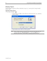
Page 21: ...tings passwords time and date screen contrast as well as managing the storage of recipe and history files Additionally memory and other system information can be viewed Calibrating the Touchscreen The touchscreen of the OIT is fully calibrated before it leaves the factory so you shouldn t need to adjust it However with time the touchscreen may need to be recalibrated 4To calibrate the touchscreen ...

Page 22: ...saving any changes Apply Save the current settings without closing the System Settings dialog OK Save the current settings and close the System Settings dialog 4 Click on the Network tab to configure network settings The Network dialog is displayed 5 The Network tab allows configuration of the IP settings The default setting is Auto Get IP Address Use this setting if the OIT will provide an IP add...

Page 23: ...me date settings The time date dialog is displayed 8 Configure appropriate time and date settings 9 Click on the Security tab to display the security settings dialog Here you can select your system passwords 1010 1007 Rev 05 OIT Local Setup 19 ...

Page 24: ...oad data to the OIT from a PC or memory module Reserved Password Not used at this time 11 The new password must be entered and then entered again to confirm As the password is entered into the confirm field an indicator will show if the two passwords match 12 Click on the History tab to display the History dialog This is where data stored in the OIT can be cleared 1010 1007 Rev 05 20 Silver Plus S...

Page 25: ... the Clear button is clicked 13 Click on the Backlight tab to display the Backlight dialog The Backlight tab adjusts the brightness of the OIT s backlight Use the mouse or touchscreen to roll the wheel Rolling to the left decreases the brightness rolling to the right increases the brightness System tags Backlight Up Backlight Down and Backlight Index can be used to adjust the brightness at runtime...

Page 26: ...If the Eject button is pressed the CF card must be removed and re inserted before the OIT will recognize Note that USB devices will not be displayed Viewing System Information 4 To view system information 1 Open the Setup Toolbar as described above and click the System Information icon A dialog will be displayed with two tabs 2 Click on the Network tab to display the current IP settings 1010 1007 ...

Page 27: ...e USB or CF device by EasyBuilder or Project Manager Download Project Transfer data from the USB CF to the OIT Upload Project Transfer data from the OIT to the USB CF Restart Project and exit Close the dialog and restart the OIT Cancel Close the dialog without transferring Restart after download upload When checked the OIT will restart after the transfer Time Remaining The dialog will automaticall...

Page 28: ...ject Files When checked the OIT will check the specified folder for project data and transfer it if it exists Download History Files When checked the OIT will check the specified folder for history data and transfer it if it exists History data includes Recipe Event Log and Data Log data 1010 1007 Rev 05 24 Silver Plus Series Installation Operation Manual ...

Page 29: ...s Port A and Port B see Figures 1 2 below The three software controlled ports are COM1 COM2 and COM3 Each software controlled communications port can only be selected for one communication type Once a communication type is selected for one of these software controlled ports that port cannot be used for another communication type Each of these communication ports has between one and three communica...

Page 30: ...COM Ports for the HMI5080 HMI5104 HMI5121 HMI5150 1010 1007 Rev 05 26 Silver Plus Series Installation Operation Manual ...

Page 31: ...COM Ports for the HMI5056 5070 1010 1007 Rev 05 Connect the OIT to the PLC or Controller 27 ...

Page 32: ...o RS485 2 Wire PLC Controllers with COM1 configured for RS485 2 Wire and COM3 configured for RS485 2 Wire splitter P N 7431 0111 is needed 1010 1007 Rev 05 28 Silver Plus Series Installation Operation Manual 5 TX RX 1 TX RX 1 GND 1 2 9P OIT COM1 RS485 GND 5 TX RX 1 1 TX RX 1 2 9S NOTES Shield wire must be terminated to connector metal shell 1 1 1 WHT BRN WHT GRN BLU 9 6 COM3 RS485 GND 5 TX RX 3 9 ...

Page 33: ...f Hex Extender F F 4 40X0 236 ZP COM1 RS485 4W Label DE9S Connector Backshell 1 00 COM3 RS485 Label 2 00 DE9P Connector Backshell 4 40 x 1 2 Retainer Screw 2 places P N Label Approx 12 00 3 RX 1 RX 1 GND 1 2 9P OIT COM1 RS485 4W TX 1 3 RX 1 1 RX 1 2 9S NOTES Shield wire must be terminated to connector metal shell 1 1 1 WHT BRN BRN WHT GRN 5 4 COM3 RS485 GND 5 TX RX 3 6 TX RX 3 9 9S 1 WHT ORN ORN B...

Page 34: ... RX 1 GND 1 2 9P OIT COM1 RS485 4W TX 1 3 RX 1 1 RX 1 2 9S NOTES Shield wire must be terminated to connector metal shell 1 1 1 WHT BRN BRN WHT GRN 5 4 COM3 RS232 GND 5 TXD 3 7 RXD 3 8 9S 1 WHT ORN ORN BLU TX 1 TX 1 8 7 TXD 3 RXD 3 GRN BLU GND TX 1 5 4 Standoff Hex Extender F F 4 40X0 236 ZP COM1 RS485 4W Label DE9S Connector Backshell 1 00 COM3 RS232 Label 2 00 DE9P Connector Backshell 4 40 x 1 2 ...

Page 35: ...ler 31 5 TX RX 1 TX RX 1 GND 1 2 9P OIT COM1 RS485 GND 5 TX RX 1 1 TX RX 1 2 9S NOTES Shield wire must be terminated to connector metal shell 1 1 1 WHT BRN WHT GRN BLU 8 7 COM3 RS232 GND 5 RXD 3 8 TXD 3 7 9S 1 GRN BRN BLU TXD 3 RXD 3 Standoff Hex Extender F F 4 40X0 236 ZP COM1 RS485 Label DE9S Connector Backshell 1 00 COM3 RS232 Label 2 00 DE9P Connector Backshell 4 40 x 1 2 Retainer Screw 2 plac...

Page 36: ... RXD1 TXD1 GND 2 3 9S OIT COM1 RS232 GND 5 RXD1 2 TXD1 3 9P NOTES Shield wire must be terminated to connector metal shell 1 1 1 WHT BRN WHT GRN BLU 6 4 COM2 RS232 GND 5 RXD2 6 TXD2 4 9P 1 GRN BRN BLU TXD2 RXD2 Standoff Hex Extender F F 4 40X0 236 ZP COM1 RS232 Label DE9P Connector Backshell 1 00 COM2 RS232 Label 2 00 DE9S Connector Backshell 4 40 x 1 2 Retainer Screw 2 places P N Label Approx 12 0...

Page 37: ...as well as for communicating with supported Ethernet PLCs and protocols The connector is wired just like the RJ45 Ethernet connector on a PC The Ethernet connection to a PLC controller will vary with each PLC controller Some will require a straight through connection while others require a crossover connection See Maple Systems website for cable drawings of Ethernet cables 4To connect a single PLC...

Page 38: ...1010 1007 Rev 05 34 Silver Plus Series Installation Operation Manual ...

Page 39: ...ce VGA or higher resolution monitor set for 16 Bit color 1024 x 768 pixel mode Microsoft mouse or compatible pointing device One available Ethernet port Microsoft Windows XP 2000 or Vista Connecting OIT to Computer Before you start your first project the OIT should be connected to the computer so that the project can be downloaded after creating it You should also connect the PLC that you are usin...

Page 40: ...th the following filenames HMI5056 MTP sample project for the HMI5056 HMI5070 MTP sample project for the HMI5070 HMI5080 MTP sample project for the HMI5080 HMI5104 MTP sample project for the HMI5104 HMI5121 MTP sample project for the HMI5121 HMI5150 MTP sample project for the HMI5150 Setting the System Parameters Whenever you begin a new project you should always set the system parameters before y...

Page 41: ...m Parameters dialog box appears 3 The dialog box has six tabs Device Model General Security Font Language Editor and Extend Memory Select the Device tab 4 Click New The Device Properties Dialog appears 1010 1007 Rev 05 Creating Your First Project 37 State toolbar ...

Page 42: ...log appears 6 Set Com Port Settings that match your PLC Reserved settings are specific to each type of PLC Refer to the Controller Information Sheet for that PLC for more details Click OK twice to return to System Parameter Settings dialog 1010 1007 Rev 05 38 Silver Plus Series Installation Operation Manual ...

Page 43: ... using a function key in the startup window to call this popup window however this window must first exist before we can map the function key to it which is why we are creating the popup prior to creating the startup window Multiple popup windows can be displayed on a full screen window The windows may overlap each other or be moved anywhere onscreen This section will show how to create a scale an...

Page 44: ...e Window 11 1 From the Window menu click Open Window The Open Window dialog box appears 2 Click New The Select Window Style dialog box appears 1010 1007 Rev 05 40 Silver Plus Series Installation Operation Manual ...
Page 45: ... dialog box appears 7 Click on the white color box then click OK The color box will reflect the color that you have chosen 8 In the Popup window section enter 60 for the X position Enter 60 for the Y position 9 Click OK The Open Window dialog will reappear 10 In the Open Window dialog highlight Window 11 then click on the Open button Window 11 now appears on your work area configured to the size i...

Page 46: ...he Objects menu click Meter Display The New Meter Display Object dialog box appears 2 Type Meter Display in the Description box 3 Click the Outline tab to configure the meter style 1010 1007 Rev 05 42 Silver Plus Series Installation Operation Manual ...

Page 47: ... meter display just created Click to place the meter display in Window 11 17 Now resize the meter so that it is a better fit on the popup window Double click on the meter display to re display the attribute dialog 18 Click the Profile tab to display the profile form 19 Enter the following values X 45 Y 13 Width 120 Width 120 20 Click OK 4To create a numeric register on Window 11 1 From the Objects...

Page 48: ...n Set Word The New Set Word Object dialog box appears 2 Type Increment Button in the Description box 3 Click on the pull down box of the Mode box and select Press and hold increment JOG 4 Enter 1 in the Inc value box 5 Enter 100 in the Upper limit box 6 Click on the pull down box of JOG Delay and select 0 5 second 1010 1007 Rev 05 44 Silver Plus Series Installation Operation Manual ...
Page 49: ...7 Click the Shape tab 1010 1007 Rev 05 Creating Your First Project 45 ...

Page 50: ...see a white square outline that is attached to your cursor in the work area This represents the increment key just created Click to place the increment key on Window 11 15 Use the blue handles surrounding the key to drag the increment key to the desired size and then place to the left of and below the numeric object 4To create a decrement key on Window 11 1 We are going to create the decrement key...

Page 51: ...ppears 6 In the General tab section change the Description to Decrement Button 7 Click on the pull down box of the Mode Attribute and select Press and hold decrement JOG 8 Enter 0 in the Attribute Bottom limit box 9 Click the Shape tab 10 Click Shape library The Shape Library dialog box appears 11 Scroll through the selections to selection 4 Click the shape then click OK The shape should appear in...

Page 52: ...ct what you have chosen 9 Now click the Label tab and make sure Use Label checkbox is not checked Click OK 10 On the main screen of EasyBuilder you will see a white square outline that is attached to your cursor in the work area This represents the function key just created Move this key to the upper right corner of the screen and click to place 11 Now double click on this key to redisplay the att...

Page 53: ...the Window menu click 1 MTP1 Window10 Window 10 will now appear in your workspace 4To place text on Window 10 1 From the Draw menu click Text The New Text Object dialog box appears 1010 1007 Rev 05 Creating Your First Project 49 ...

Page 54: ...e word text in the Content box and type This is the Startup Screen 7 Click OK 8 On the main screen of EasyBuilder you will see a white rectangle outline that is attached to your cursor in the work area This represents the text box just created Center the rectangle somewhere on the top third portion of the work area and then click The text box This is the Startup Screen will appear 1010 1007 Rev 05...

Page 55: ...From the Objects menu click Button Function Key The New Function Key Object dialog box appears 2 Type On Button in the Description box 3 Click Display Popup Window 4 Type 11 in the Window No Box 1010 1007 Rev 05 Creating Your First Project 51 ...

Page 56: ...5 Click the Shape tab to display the shape dialog 1010 1007 Rev 05 52 Silver Plus Series Installation Operation Manual ...
Page 57: ...e library The Shape Library dialog box appears 7 Click button1 in the Shape library box 8 Scroll through the selections to selection 23 Click the shape then click OK The shape will appear in the Shape tab 1010 1007 Rev 05 Creating Your First Project 53 ...

Page 58: ...n the Align box 15 Type ON in the Content box 16 Click OK 17 On the main screen of EasyBuilder you will see a white square outline that is attached to your cursor in the work area This represents the function key just created Center the square somewhere on the bottom left portion of the work area and then click The function key will appear 18 Double click on the function key The Function Key Objec...

Page 59: ...alog box appears 6 In the General tab section change the Description to Off Button 7 Click on Close Window Enter 10 for Window number 8 Click on the Label tab Type OFF in the Content box 9 Click on the Profile tab 10 Enter 196 for the X position Enter 168 for the Y position 11 Click OK 12 On the main screen of EasyBuilder you will see the second function key that you just created move to the lower...

Page 60: ...Saving your first project 1 From the File menu click Save As The Save As dialog box appears 2 Use the drop down menus to locate the project folder 3 In the File name text box type MTPrj1 4 Click Save The file is saved onto your computer hard drive and the main screen of EasyBuilder reappears 4Compiling your first project 1 From the Tools menu click Compile The Compiling dialog box appears 1010 100...

Page 61: ...s the OIT s current IP setup information is displayed but is not changeable To change the IP address select IP Address Get From Below and enter the data 5 Once the IP Address has been established the project can be downloaded From EasyBuilder s Tools menu select Download Or click the Download icon 6 Enter the OIT s IP address and Download password The default download password is 111111 The defaul...

Page 62: ...1010 1007 Rev 05 58 Silver Plus Series Installation Operation Manual ...

Page 63: ...rtup screen of the project You can test any objects you have created which require touchscreen input by clicking on them In this example clicking on the increment key simulates the key as it is pressed on the touchscreen Simulation Mode always uses the compiled version of the project that you have created the xob file Therefore you must save and compile any changes you make to the project before y...

Page 64: ...the Online Simulator The Open Project dialog box appears 3 Click on the compiled project file that you wish to simulate 4 Click Open The simulation screen appears 5 To end on line simulation right click in the simulation screen and click Exit Online simulation requires a direct connection between the PC and the controller It is not necessary to have the OIT connected The OIT s COM1 RS232 connectio...

Page 65: ...ilder easily This will pave the way for actually creating graphics objects in later chapters EasyBuilder 5000 includes extensive online help From any dialog box within the software click on the HELP button or press the computer s F1 key The Project Manager The Project Manager utility sets the communications parameters that are used by the computer when communicating to the OIT The utility can also...

Page 66: ...ng illustration shows the various commands available Communications Password Settings Settings Button 1 Download Upload passwords default 111111 1010 1007 Rev 05 62 Silver Plus Series Installation Operation Manual ...

Page 67: ...e to OIT 2 Start Project Manager 3 Click Build Download Data for CF USB Disk The Project Manager dialog appears 4 Insert CF card or USB jump drive into PC Note the folder that represents the USB CF device 5 Click Browse to select the folder that represents the USB CF device 6 Check the boxes that will be the sources for your data and browse to the appropriate file for that source 7 Click Build Eas...

Page 68: ...of the print server through Project Manager The EasyPrinter utility must be running on the PC that is hosting the networked printer from which you wish the Silver Plus Series OIT to print 1010 1007 Rev 05 64 Silver Plus Series Installation Operation Manual ...

Page 69: ...uilder 5000 and can also open an existing Recipe file for editing on the PC The following choices are available on the File menu New Creates a new recipe file Open Opens a existing Recipe file Import CSV File Imports an existing CSV file 1010 1007 Rev 05 Using EZware 5000 65 ...

Page 70: ...cipe Editor are also supplied 4To edit a recipe 1 Click on the Data Format list and select Example The Set Data Format dialog will update In the Address Range fields set the From field to 0 and the To field to 4999 Click on each item in the Data Format list for details 2 Click the OK button and a File Open dialog will appear to select the RCP file to open Select Example rcp 3 Click the Open button...

Page 71: ... the OIT Upload Receives a compiled project file from the OIT to be stored on the computer For more information about printing see the Systems Configuration Settings Printer tab section later in this chapter Simulation Settings On line Simulation Opens a compiled project xob in on line simulator mode Off line Simulation Opens a compiled project xob in off line simulator mode 1010 1007 Rev 05 Using...

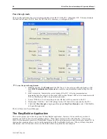
Page 72: ...l be connected to the PC 4 Destination COM Port Set COM settings for the OIT that will be connected to the PLC 5 Click Start Pass through to begin passthrough and Stop Pass through to end Click Exit to exit pass through mode That s all there is to Project Manager The EasyBuilder Application This section guides you in how to operate the EasyBuilder application however it does not show you how to pr...

Page 73: ...The following illustration is used for reference to the following sections 1010 1007 Rev 05 Using EZware 5000 69 ...

Page 74: ...ew icon in the Standard toolbar The EasyBuilder dialog box appears 2 Select the OIT model you intend to use with your project A project s display mode may be changed after the initial selection has been made To set Display Mode select Edit System Parameters and select the Model tab To change the Display Mode resize the window s resolution to fit the mode selected 1010 1007 Rev 05 70 Silver Plus Se...

Page 75: ...3 Click OK The System Parameter Settings dialog appears 1010 1007 Rev 05 Using EZware 5000 71 ...

Page 76: ...p the Device Properties dialog 5 Select the PLC option button and then select the PLC type from the drop down menu Configure any necessary COM ports and click Settings to bring up the COM Port Settings dialog 1010 1007 Rev 05 72 Silver Plus Series Installation Operation Manual ...

Page 77: ... ask you if you would like to save the project Then the main screen of EasyBuilder will remain but with no work area displayed You must now use the Open or New commands to edit a project 4To save an existing project 1 On the File Menu click Save or click the Save icon in the Standard toolbar 2 If the project already has a name then the project will automatically be saved If this is a new project t...

Page 78: ... graphics libraries from the cmp file 4To exit EasyBuilder On the File Menu click Exit or click on the standard windows Close icon in the upper right corner Editing and Creating Screen Objects This section shows how to manipulate graphics objects that are placed onto the work area of EasyBuilder We will use examples from sample projects that are included with the EasyBuilder software HMI5057 MTP H...

Page 79: ...Using the Window Tree to display window screens 1 The Window Tree combines into a single tree a list of all of the windows in a project and all of the objects on each window Using the 5056DEMO MPT project the following should be seen 2 Notice that the tree displays the title for each window next to the window number This makes it easy to determine windows have been created for a project The asteri...

Page 80: ...election of a particular object especially on crowded screens or screens where objects may be overlapping 4 To display the object s attribute dialog box double click the Object ID in the Window Tree 4Using the grid function One option is to have the work area covered with grid lines These grid markings can be helpful when trying to align objects that are created on the work area If grid lines are ...

Page 81: ...earance to graphics objects 4To use the snap option 1 The Grid option must be enabled 2 On the Option Menu click Grid Snap The Grid Snap Settings dialog box appears 3 Click the Snap checkbox 4 Click OK Finally you will find that you can move objects by selecting them with the mouse cursor and dragging them to a new location However you may find it difficult to select an object without accidentally...

Page 82: ...he lower right corner of the highlighted objects Notice that a rectangle is formed as you do this In this example move the mouse to the right and below Fill Level 4 Release the mouse button The rectangle outline changes to small clear square blocks around the perimeter of the objects selected Now both objects are selected If you do not completely enclose any graphics objects you wish to highlight ...

Page 83: ...e appropriate icon in the Standard toolbar 2 Select the graphics object or objects you wish to cut or copy 3 Click Cut to copy and remove the graphics object s from the work area or click Copy to copy the graphics object s Using Window_12 select the Motor Speed text box and then press CTRL X to cut the object from the work area 4 Objects cut or copied from one window can be pasted into other windo...

Page 84: ... side of one object to the left side of the next object The Y Distance setting is the distance from the bottom of one object to the top of the next object X Distance Y Distance These settings determine the spacing in pixels between objects Quantity X Quantity Y These settings determine the number of copies to be made along the X axis horizontal and the Y axis vertical Adjust Distance This is the o...

Page 85: ... that you are able to move the selected object Move the object by clicking on it and dragging the object to the proper position on the work area 4To resize a graphics object 1 Select the object to be resized 2 To resize the object move the mouse cursor over one of the small black squares The cursor changes to a double arrow icon to indicate that it is in resizing mode 3 Click and drag the mouse to...

Page 86: ...ording to their Object ID tag Alongside each ID tag is the PLC or OIT memory identifier Grouping Objects When creating graphics on a window you may create a complex graphic that is actually composed of several simpler objects overlaid onto each other This numeric display with increment and decrement button is an example of grouped objects This numeric display is actually composed of three separate...

Page 87: ...ick the UnGroup icon from the Manager toolbar 3 All objects within the group can now be copied deleted or moved separately Layering Objects Graphics objects can be overlaid upon each other When layered the graphics object on the topmost layer will be completely seen How much of the other graphics objects are seen depends on what is on top of them The following layer commands help to position the o...

Page 88: ...e layered objects Again select the layered rectangle from Window_12 3 From the Edit menu click Layer then PreviousLayer or click the PreviousLayer icon from the Manager toolbar Note that the rectangle covers the circle but not the arc 4 From the Edit menu click Layer then NextLayer or click the NextLayer icon from the Manager toolbar Note that the rectangle recedes behind the circle and the arc No...

Page 89: ...4Using the nudge top bottom left and right commands 1 Select one of the layered objects or a group of objects in the work area of EasyBuilder 2 From the Edit menu click Nudge then select the direction of the nudge or click the appropriate icon from the Manager toolbar Aligning Objects Alignment can be used to quickly align two or more objects Aligning justifies objects to the desired position of t...

Page 90: ...n For this example select the three rectangle objects of Window_12 2 From the Edit menu click Align then Right or click the appropriate icon from the Manager toolbar 3 From the Edit menu click Undo to put the objects back in their original position 4Using the align top command 1 Select the objects you wish to align For this example select the three rectangle objects of Window_12 1010 1007 Rev 05 8...

Page 91: ... to align For this example select the three rectangle objects of Window_12 2 From the Edit menu click Align then Bottom or click the appropriate icon from the Manager toolbar 3 From the Edit menu click Undo to put the objects back in their original position 4Using the align horizontal center command 1 Select the objects you wish to align For this example select the three rectangle objects of Windo...

Page 92: ...ng the align vertical center command 1 Select the objects you wish to align For this example select the three rectangle objects of Window_12 2 From the Edit menu click Align then Vert Center or click the appropriate icon from the Manager toolbar Centering is based on the vertical center of the top most object 3 From the Edit menu click Undo to put the objects back in their original position 1010 1...

Page 93: ...f Window_12 of the sample project 4The make same width command 1 Select the objects you wish to make the same width For this example select the left and center rectangle objects of Window_12 2 From the Edit menu click Make Same Size then Width or click the appropriate icon from the Manager toolbar 4The make same height command 1 Select the objects you wish to make the same height For this example ...

Page 94: ...ger toolbar Making Objects the Same Color This feature can be used to make two or more drawn objects the same color 4 To make objects the same color 1 Select the objects that you wish to make the same color EZware will choose the color of the last selected object 2 Select Edit Make Same Color The selected objects will all change color to the same color as the last selected object 1010 1007 Rev 05 ...

Page 95: ...click Flip Vertical or click the appropriate icon from the Manager toolbar 3 From the Edit menu click Undo to put the left triangle object back in its original position 4To flip horizontally 1 Select the object you wish to flip horizontally For this example select the right triangle object of Window_12 2 From the Edit menu click Flip Horizontal or click the appropriate icon from the Manager toolba...

Page 96: ...h object position and size can be locked by using the Pin button When the object is locked its position and size cannot be changed 1 Select the object you wish to lock 2 From the Edit menu click Pinned or click the appropriate icon from the Manager toolbar 3 To unlock the object deselect Pinned from the Edit menu or click the appropriate icon from the Manager toolbar 1010 1007 Rev 05 92 Silver Plu...

Page 97: ...configured using EasyBuilder From the Edit menu click System Parameters The System Parameter Setting dialog box appears The dialog box has seven tabs Device Model General Security Font Language Extend Memory and Printer Server PLC Settings Configuration 1010 1007 Rev 05 Creating Your First Project 93 ...

Page 98: ...tisfactory 2 Select the PLC button and then select your PLC from the drop down menu 3 There are two choices for Location either Local or Remote Select Local if the PLC will be connected directly to the OIT Select Remote if the PLC will be connected to a remote OIT If Remote is selected then click Settings and configure the appropriate IP settings 4 IP Address Enter the address of the remote OIT 5 ...

Page 99: ...Controller Information Sheets or the PLC manufacturer s operations manual for information on the communications parameters required by the PLC These parameters have to match the PLC settings 11 Click OK 12 Interval of Block Pack Words Determines how many words are read from the PLC in one communication cycle For more information on this feature see PLC Block Pack at the end of this chapter 13 Clic...

Page 100: ...oller Information Sheet for more information 4 Port No Assign a TCP IP port so that another OIT can access this port For more information see the Using Remote HMIs section 5 Clock Source Select internal HMI RTC or External Device 6 Printer Type Select type of printer 1010 1007 Rev 05 96 Silver Plus Series Installation Operation Manual ...

Page 101: ...og 1 In the Model tab select a different display size from the HMI model drop down box and click OK 2 If the new display is smaller than the existing display the project will automatically resize If the new display size is larger then the existing display the Resize Popup Windows Objects dialog appears 3 Check Resize pop up windows and Resize objects and then click OK The project will automaticall...

Page 102: ...ressed Screen Saver sets the number of minutes 0 255 that the screen will go untouched before the screen saver window is activated If the value none is selected then the screen saver is disabled Saver Window No designates the window that will be used as the screen saver 3 Option Startup Window No Selects the window number that will be displayed every time the OIT is started up Extra No of events T...

Page 103: ...nables an extra 64K of recipe data 4 Keyboard Lists the windows that have been configured as keyboards Security The Security tab determines the table of user passwords Up to 12 sets of password can be set where one or all users can be set or disabled Each user can be individually enabled and has a unique password and combination of any six Access Classes A F Only numbers are allowed for password 1...

Page 104: ...splay the message defined as Message 1 in the System Message object There are a number of local OIT addresses that can be used with the security features Address Description Data Type Notes LB9050 Reset security level to 0 no security Boolean Set momentarily to trigger LB9060 Invalid password Boolean Set by the OIT when an invalid password is entered Must be explicitly reset LB9061 Load new passwo...

Page 105: ...omentarily LW9514 LW9515 New password user 8 32 bit unsigned Loaded into security system when LB9061 is set momentarily LW9516 LW9517 New password user 9 32 bit unsigned Loaded into security system when LB9061 is set momentarily LW9518 LW9519 New password user 10 32 bit unsigned Loaded into security system when LB9061 is set momentarily LW9520 LW9521 New password user 11 32 bit unsigned Loaded int...

Page 106: ...Extended Memory Used to set parameters for saving data to CompactFlash and USB memory storage 1010 1007 Rev 05 102 Silver Plus Series Installation Operation Manual ...

Page 107: ...ata for each register that is displayed on screen For instance if you have five data fields configured on the OIT to monitor R1 R2 R3 R4 and R5 of a GE PLC then the OIT sends five separate commands to the PLC to update these fields This is the slowest method of updating the registers but it does have the advantage that the update rate does not depend on having the PLC registers all together R1 R5 ...

Page 108: ... R10 and R40 with the PLC block pack is set to 10 the OIT will send two commands one to get R1 and R10 another to get R40 If the PLC block pack were set to 0 then the OIT would have sent three commands In this case however the three commands probably take less time than the two commands because the OIT has to receive data for ten registers R1 R10 in one command takes more time than the overhead as...

Page 109: ... it is covered up by another window Windows can be moved around OITdisplay to allow portions of other windows to come into view The Silver Plus Series has four basic types of windows available for use Base windows a Common window System Message window and a Fast Selection window Base windows are the windows that you will most often use The common window and fast selection window are two windows re...

Page 110: ...To close a window 1 You will notice two small icons located in the upper right hand corner of each window the minimize icon the maximize icon and the close icon To close a window click the close icon associated with that window These icons show in the window if minimized Otherwise the icons are located on the rightmost end of the menu bar of EasyBuilder Creating a New Window Whenever you create a ...

Page 111: ... available to be created as you desire for your project in order to create new windows the following steps must be performed 4To create a new window 1 From the Window menu select Open Window The Open Window dialog box appears 2 Click New The Select Window Style dialog box appears 3 Click Base Window If the Fast Selection and Common Window buttons appear grayed out 1010 1007 Rev 05 Creating Windows...

Page 112: ...eserved for the Common Window and the Fast Selection window and several are reserved for internal use Therefore you can assign 10 1999 to any window you create When you initially create a window EasyBuilder will automatically assign the lowest available number to the window However you can assign any number within the allowed range In this manner you can group windows together that may share some ...

Page 113: ...umeric keypad in one popup window that can be moved aside or closed when not needed The keypad can be triggered to pop up when needed or appear with a keypress The allowable range for the width is 100 320 640 for the HMI5080 5104 5121 pixels The allowable range for the height is 100 240 234 for the HMI5056 5070 480 for the HMI5080 5104 5121 pixels Monopoly Feature The monopoly feature is used to m...

Page 114: ...alog box that asks the OIT operator if some step in the control process has been performed The dialog box would have Yes and No function key options which with the monopoly feature enabled the OIT operator must press before continuing Assigning Underlay Windows An Underlay Window is a Base Window that is displayed at the same time as the Base Window that calls it Each full size Base Window can dis...

Page 115: ... color and size etc are not displayed on the base window Active objects can be overlaid on top of each other over two or more underlay windows For example a Set Bit object that is configured to set an OIT local bit LB0 is located at X 20 Y 50 for Underlay Window 1 Another Set Bit object that controls LB1 is placed on Underlay Window 2 at the same location When the Base Window displays these two wi...

Page 116: ...Setting dialog box 10 Click the pull down arrow of the Pattern box The Pattern Style dialog box appears 11 Select the pattern you wish to use then click OK The Window Setting dialog box reappears 12 Click OK in the Color dialog box to go back to the Window Setting dialog box Click Close to return to the EasyBuilder main screen Deleting a Window Before any window can be deleted from a project the w...

Page 117: ...played is generally overlaid over all other windows that are on display Think of calling a popup window as opening another active window for display 4To call a popup window using a function key object 1 From the Objects menu select Function Key The New Function Key Object dialog box appears 2 In the General Tab check the Display Popup Window option button Note that the Close this popup window when...

Page 118: ... assign internal data register LW10 to a PLC Control Object Change Window and the number 3 is placed into this register then the OIT will display Screen 3 Finally it will put the number 3 into LW11 This allows the PLC to confirm that the Screen has been properly displayed by the OIT You can create as many PLC Control Objects as you need each object is universal and is not dependent upon which OIT ...

Page 119: ...t the PLC to call up a popup window that is to be overlaid on top of other windows already open then there are two methods used to do this Direct Window Object Indirect Window Object Unlike the PLC Control Object the Direct and Indirect Window Objects are only active for the windows into which they are placed The Direct Window Object is used to display a popup window using a PLC coil The OIT conti...

Page 120: ...o you want to call from the drop down menu under the Attribute heading 4 Click OK to return to the main screen of EasyBuilder The mouse cursor will have a square object that represents the size of the popup window 5 Place the Direct Window object where you want the popup window to appear 6 You can resize the object after you have placed it by clicking on the object and dragging on the sizing handl...

Page 121: ...d to use to display a base window Here are some suggestions If you want to clear the OIT display of all open windows and display a new full screen window then use the PLC Control Object function or select the Change Window option in the Function Key Object The PLC Control Object is global meaning it does not matter which windows are currently on display so the OIT will always monitor the PLC addre...

Page 122: ...ction Key Object dialog box is displayed 2 Select the Return to Previous option button 3 Configure the rest of the function key and then click OK 4 Place the function key object onto the full sized base screen Placing a return to previous function key onto a popup window will not work Using a function key to close a window You can configure a function key to close any popup window that is currentl...

Page 123: ... window 4 Press OK The Open Window dialog box reappears with the Common Window selected 5 If you wish to open the common window click Open Otherwise click Close to return to the main screen of EasyBuilder Displaying the common window above below the base screen This setting resolves the conflict that can occur if a graphics object on the common window occupies the same space on the OIT display as ...

Page 124: ...ters dialog box appears 2 Select the General tab In the Common Window frame box select either Above base screen or Below base screen for the Attribute box 3 Click OK to return to the main screen of EasyBuilder Active graphics objects objects that display information or graphics according to a data value in a PLC register or coil take precedence over passive graphics objects 1010 1007 Rev 05 120 Si...

Page 125: ...common window the Start Pos Style Frame and Background settings are ignored by the OIT For this example let s use Window 30 as the alternate common window 3 Create another full screen base window that can be displayed along with the common windows such as a startup window Let s use Window 10 the initial window for our example 4 On Window 10 create a Function Key object that is used to change the c...

Page 126: ...dows are active You may also create projects that require a window that is always accessible like a common window but not always displayed For example you may want a numeric keypad available for any data entry however a keypad takes precious space on the OIT display Ideally it should appear on screen only when a key was pressed and then by pressing another or the same key the keypad should disappe...

Page 127: ...ection earlier in this chapter for more information Notice that the default size is Width 80 and Height 200 The default was selected to create a sidebar that contains function keys to display other windows The example below illustrates how the Fast Selection Window can be used for this purpose 4 Press OK The Open Window dialog box reappears with the Fast Selection window selected 5 If you wish to ...

Page 128: ...e fast selection key 1 Select Edit System Parameters The System Parameters Setting Dialog appears Select the General tab 2 In the Fast selection button section select Enable from the Attribute drop down menu 3 Select either right or left from the Position drop down menu to select whether the button will appear in the right lower corner or left lower corner of the display 4 Click Settings Click the...

Page 129: ...xample steps you through creating six full screen base windows enabling the Task Bar and creating a Fast Selection window to call up the six screens We will start with the following six screens Next create a new Fast Selection window using default settings For this example we will create six Function Key objects that change windows Configure each Function Key object with the Change Window attribut...

Page 130: ...oading the project file to the OIT the following initial screen should be shown Press the Fast Selection key to activate the Fast Selection window Press one of the Function Keys to switch to another full screen window 1010 1007 Rev 05 126 Silver Plus Series Installation Operation Manual ...

Page 131: ...ion windows System Message Window EasyBuilder has two Windows designated as System Message windows Window 5 is designated as the PLC Response Window that pops up automatically when the OIT loses communications with the PLC Window 6 is designated as the HMI Response window which will pop up automatically with the OIT loses communications with a another OIT that is remotely connected Both of these w...

Page 132: ...1010 1007 Rev 05 128 Silver Plus Series Installation Operation Manual ...

Page 133: ... Draw menu click Line or click the Line icon in the Draw toolbar The Properties dialog box appears 2 Click the pull down box from the Color box The Color dialog box appears 3 Click on the appropriate color box then click OK The color box should reflect what you have chosen 4 Click on the line thickness that you want to use 5 Move the mouse cursor over to the work area of EasyBuilder onto the windo...

Page 134: ...Ellipse Circle Tool The ellipse tool is used to create ellipses or circles Each ellipse created has four parameters associated with it size thickness color and filled 4To create an ellipse 1 From the Draw menu click Ellipse Circle or click the Ellipse Circle icon in the Draw toolbar The Attributes dialog box appears 2 If the interior of the ellipse is to be filled with a color check the Filled box...

Page 135: ...Two additional settings appear 3 If you want to fill the polygon with a solid color then select a color for the Interior box Click Pattern Style to display the Pattern Style dialog box Select the upper left most pattern for a solid color If you want to use a pattern for the filled section of the polygon then select from the available patterns and click OK to exit the Pattern Style dialog box In th...

Page 136: ...loses and the main screen of EasyBuilder reappears with the Scale Object displayed Scale lines are most often used when creating bar graphs scale meters and trend graphs The Free Line Tool The Free Line Tool allows you to draw lines in a free form fashion 4 To draw a free form line 1 From the Draw menu select Arbitrary line or click on the Free line icon on the draw tool bar The Properties dialog ...

Page 137: ...r The Properties dialog appears 2 Configure any properties for your line 3 Move your cursor over the EasyBuilder work area A crosshair will appear Move your crosshair to where you would like to begin your lines 4 Click your mouse to begin your line Move your mouse to the point where you would like your first line to end and your next line to begin and click your mouse again Repeat this step until ...

Page 138: ... would like to appear in the text box 7 Click OK The main screen of EasyBuilder reappears with the outline of the text box tagged to the cursor in the upper left corner of the work area 8 Move the text box to the area you wish to place it on the window and click 9 The text box appears with small square boxes around the perimeter Click on another area of the window to end the edit session or double...

Page 139: ...cs are more difficult to modify they offer the most flexibility in customizing the graphic object In most cases you won t need to know the difference between a shape graphic and a pixel based graphic You will base your selection on what looks good However keep the following comparisons in mind Shapes Pictures Ease of Creation Can be created using EasyBuilder Must be created using a desktop graphic...

Page 140: ... To use a shape 1 From the Draw menu click Shape Or click the Shape icon in the Draw toolbar The New Shape Object dialog box appears 1010 1007 Rev 05 136 Silver Plus Series Installation Operation Manual ...

Page 141: ... corner of the work area 7 Move the shape to the location desired and click The shape appears with small square boxes around the perimeter of the shape 8 The shape can be resized or you can edit the shape s parameters by double clicking to enter the Shape Object s Properties dialog box or by dragging on the resizing handles on the corners of the object Using a Predefined Picture You can select fro...

Page 142: ...he Library section by double clicking 4 Use the scroll bar to view available bitmaps Click on the bitmap that you want 5 Click OK The New Picture Object dialog box reappears The picture that you selected will be displayed in this dialog box 6 Click OK The main screen of EasyBuilder reappears with an outline of the bitmap object in the upper left corner of the work area 1010 1007 Rev 05 138 Silver ...

Page 143: ... the group library for easy retrieval All libraries are accessed from the Library menu or by clicking the appropriate icon in the Standard toolbar What are states Many of the graphics objects ex Set Word Object or Moving Shape Object use states to determine which picture to display Shapes and pictures can be configured with up to 255 different states Each shape can be configured to show a differen...

Page 144: ...zing shapes 4To create a new shape library 1 With the Shape Library dialog box displayed click New Lib The New Library dialog box appears 2 Enter a name for the new library Click OK 3 The Shape Library dialog box appears with the new library loaded Click Close 4 The new library is now available to this project but it is not stored into the Library subdirectory of EasyBuilder until the project file...

Page 145: ... interior 8 Click OK The Shape Library dialog box appears with the shape stored in the library 9 Click Close to return to the main screen of EasyBuilder 10 From the File menu click Save to save the shape to the library Important you must save before attempting to store the next shape 11 Highlight the other shape by clicking the mouse and dragging a rectangular outline so that it covers the entire ...

Page 146: ...elete from the library 4 Click Delete The shape is removed from the library 5 Click Close to go back to the main screen of EasyBuilder 6 Save the project file to permanently save changes made to the library Caution once project is saved the shape is permanently deleted from the library and cannot be replaced Finally you may want to use all or parts of an existing shape to create a new one To do th...

Page 147: ...stored in the library To change the shape you must delete the shape and store any changes you make to a new shape Using Picture Libraries EasyBuilder includes picture libraries from which you can select pictures 4To display the Picture Library dialog box 1 From the Library menu click Picture then click Call up library Or click the Call up Picture Library icon from the Standard toolbar The Picture ...

Page 148: ...ry dialog box displayed click New Lib The New Library dialog box appears 2 Enter a name for the new library Click OK 3 The Picture Library dialog box appears with the new library loaded Click Close 4 The new library is now available to this project but it is not stored into the Library subdirectory of EasyBuilder until the project file has been saved Creating and exporting pictures Although EasyBu...

Page 149: ... so that they may be replaced by another bitmap 4To delete a picture from a library 1 From the Library menu click Picture then Call up library The Picture Library dialog box appears 2 Select the library that the picture is located in 3 Click on the picture that you wish to delete from the library 4 Click Delete picture The bitmap is removed from the library 5 Click Close to go back to the main scr...

Page 150: ...libraries for access by any project Creating group objects often saves a lot of time when creating new projects because you can use the same objects repeatedly For example suppose you regularly use a scale meter similar to the following This one scale meter is actually composed of five objects Rather than waste time recreating this scale meter for each new application it would be much easier to st...

Page 151: ...ame and choose from one of the open libraries of groups 2 Select which library you would like to close then click Unattach Lib A dialog box appears asking if you really want to unattach the selected library Click Yes 3 The Group Library dialog box reappears and the library is removed from the Group library list The option of creating a new library is also available This can be very useful when org...

Page 152: ...st group not used 5 Enter a title for the new group in the Description box 6 Click OK The Group Library dialog box appears with the group stored in the library 7 Notice that any shape or bitmap libraries used to create the group object are listed for your reference in the Including library box 8 Click Close to return to the main screen of EasyBuilder 9 From the File menu click Save to permanently ...

Page 153: ... on the work area For this example select item 0 4 Click Place The main screen of EasyBuilder reappears with the group in the upper left corner of the work area 5 Move the group object to the preferred location on the window This completes our discussion on creating shapes bitmaps and group objects with EasyBuilder This chapter also provided some examples on how to use the drawing tools The next s...

Page 154: ... for use in sound libraries 1 Select Library Sound to display the Sound Library dialog 2 Click Import The Open file dialog appears 3 Browse to the sound that you want to import and click Open 4 To export a WAV file for use in other applications 1 Select Library Sound to display the Sound Library dialog 2 Highlight the WAV to export from the library table and click Export The Save in dialog appears...

Page 155: ... the delete to be permanent 4 To unattach a sound library 1 Select Library Sound The Sound Library dialog appears 2 Click Unattach Lib 3 A dialog pops up asking if you really want to unattach the library Click Yes 1010 1007 Rev 05 Creating Graphic Objects 151 ...

Page 156: ...1010 1007 Rev 05 152 Silver Plus Series Installation Operation Manual ...

Page 157: ...g the Tag Library The Tag Library is a database of register addresses with each tag representing a single address EasyBuilder gives you the option of using either Customized or System tags Customized tags are tags that you build yourself System tags are predefined tags that allow access to certain built in functions and settings You can select whether you will be using customized or system tags in...

Page 158: ...gs from the tag library to be saved into a tgl file format Once saved the file can be loaded into another project 4To save the tag library 1 Click on Save Tag File The Open dialog box appears 2 Enter the name of the file where you wish to save the data 3 Click Open 4To load the Tag Library from an existing tgl file 1 Click on the Load Tag File The Open dialog box appears 2 Browse for the tgl file ...

Page 159: ...g checkbox The Device Type list will be filled with a list of available tags Objects addressable as Register type objects will display Tags configured as Word Objects addressable as Bit type objects will display Tags configured as Bit 3 Select the desired Tag from the Device Type list to address the Object to the referenced Register Address Creating the Label Library The Label library is a databas...

Page 160: ...the Label dialog 3 Enter the Title Name for the label and how many states the new label requires For example a label Titled Start requiring 2 states to represent separate conditions where condition one status is START condition two is STOP 4 Click the OK button and the new label is added to the database The Name will appear in a selectable listing of available Labels for use with objects that supp...

Page 161: ...tates desired Click OK The Label is now contained in the Label Library and displayed when the Library is opened View text labels for the various states of each label in the Library by selecting the State to display in the pull down box 10 Once a label text has been created and you wish to change the number of states you may do so by double clicking on the desired label text On the Label Content Se...

Page 162: ...bl file that contains the labels 3 Click Open The lbl file format can not be edited The label library can also be imported and exported using a comma separated variable csv file format This format is very useful if you need to make several changes to the database When creating a new project it is easier and faster to create and edit tags as csv files 4To export the label library 1 Click Export CSV...

Page 163: ...age selected for viewing 4 To use the Multi Language features of the Label Library to display object labels in languages other than the default language Language 0 the function must be enabled Enable the Multi Language capability as detailed below Using Languages with the Label Library The Silver Plus Series supports up to eight languages for use with the Label Library text labeling In order to us...

Page 164: ...s English and English is the configured Language 0 in the Label Library pressing the English Set Word object writing a 0 to LW9134 will enable label text display in English If Set Word 1 enables French and French is the configured Language 1 in the Label Library pressing the French Set Word object writing a 1 to LW9134 will enable text display in French Continue for all Languages configured in the...

Page 165: ... OIT Reserved Local Bits System Tags Address Function Notes LB 9000 initialized as ON Bits are set ON at startup but can be reset and used as needed LB 9001 initialized as ON Bits are set ON at startup but can be reset and used as needed LB 9002 initialized as ON LB 9003 initialized as ON LB 9004 initialized as ON LB 9005 initialized as ON LB 9006 initialized as ON LB 9007 initialized as ON LB 900...

Page 166: ...vel 2 set ON LB 9053 change security to level 3 set ON LB 9054 change security to level 4 set ON LB 9055 change security to level 5 set ON LB 9060 password error ON when an invalid password has been entered LB 9061 update password set ON LB 9070 Toshiba Timer Counter write control set ON before writing to a time or counter in a Toshiba PLC LB 9100 remote HMI 1 status set on to retry connection OFF...

Page 167: ...ry connection LB 9207 PLC 1 status SN7 COM1 set on to retry connection LB 9500 PLC 2 status SN0 COM2 set on to retry connection LB 9501 PLC 2 status SN1 COM2 set on to retry connection LB 9502 PLC 2 status SN2 COM2 set on to retry connection LB 9503 PLC 2 status SN3 COM2 set on to retry connection LB 9504 PLC 2 status SN4 COM2 set on to retry connection LB 9505 PLC 2 status SN5 COM2 set on to retr...

Page 168: ...LW 9011 16bit BCD local minute LW 9012 16bit BCD local hour LW 9013 16bit BCD local day LW 9014 16bit BCD local month LW 9015 16bit BCD local year LW 9016 16bit BCD local week LW 9017 16bit local second OIT real time clock data in int format LW 9018 16bit local minute LW 9019 16bit local hour LW 9020 16bit local day LW 9021 16bit local month LW 9022 16bit local year LW 9023 16bit local week LW 902...

Page 169: ...t no LW 9134 16bit language mode LW 9150 32 words keyboard s input data ASCII LW 9200 16bit address index 0 LW 9201 16bit address index 1 LW 9202 16bit address index 2 LW 9203 16bit address index 3 LW 9204 16bit address index 4 LW 9205 16bit address index 5 LW 9206 16bit address index 6 LW 9207 16bit address index 7 LW 9208 16bit address index 8 LW 9209 16bit address index 9 LW 9210 16bit address ...

Page 170: ...thernet LW 9400 16bit error code for PLC 0 LW 9401 16bit error code for PLC 1 LW 9402 16bit error code for PLC 2 LW 9403 16bit error code for PLC 3 LW 9404 16bit error code for PLC 4 LW 9405 16bit error code for PLC 5 LW 9406 16bit error code for PLC 6 LW 9407 16bit error code for PLC 7 LW 9500 32bit user 1 s password level 1 LW 9502 32bit user 1 s password level 2 LW 9504 32bit user 1 s password ...

Page 171: ...OM3 Stop bits LW 9600 16bit PLC4 IP0 Format IP0 IP1 IP2 IP3 LW 9601 16bit PLC4 IP1 LW 9602 16bit PLC4 IP2 LW 9603 16bit PLC4 IP3 LW 9604 16bit PLC4 IP Port LW 9605 16bit PLC5 IP0 LW 9606 16bit PLC5 IP1 LW 9607 16bit PLC5 IP2 LW 9608 16bit PLC5 IP3 LW 9609 16bit PLC5 IP Port LW 9610 16bit PLC6 IP0 LW 9611 16bit PLC6 IP1 LW 9612 16bit PLC6 IP2 LW 9613 16bit PLC6 IP3 LW 9614 16bit PLC6 IP Port LW 961...

Page 172: ... remote HMI 3 IP 3 LW 9814 16bit remote HMI 3 Port LW 9815 16bit remote HMI 4 IP0 LW 9816 16bit remote HMI 4 IP1 LW 9817 16bit remote HMI 4 IP2 LW 9818 16bit remote HMI 4 IP3 LW 9819 16bit remote HMI 4 Port LW 9820 16bit remote HMI 5 IP 0 LW 9821 16bit remote HMI 5 IP1 LW 9822 16bit remote HMI 5 IP2 LW 9823 16bit remote HMI 5 IP 3 LW 9824 16bit remote HMI 5 Port LW 9825 16bit remote HMI 6 IP 0 LW ...

Page 173: ...ject the Set Bit Object and the Toggle Switch Object Each has a particular function that makes them unique but they are all constructed and used in essentially the same manner The Bit Lamp Object The Bit Lamp Object is used to represent the value of a PLC coil The object continuously reads the PLC coil and displays the corresponding shape or bitmap that is tagged to the On or Off state of the coil...

Page 174: ...ory address 4 In the Blinking frame select how you want the Bit Lamp object to operate Mode Description None Displays State 0 object when clear displays State 1 object when set Alternating Image on State 0 Alternates between state 0 and 1 object when clear displays the state 1 object when set Alternating Image on State 1 Displays the state 1 object when clear alternates between state 0 and 1 when ...

Page 175: ... the Shape form 6 Select either a shape or bitmap to represent the Bit Lamp object If you need more information on how to do this consult Chapter 6 Creating Graphics Objects 1010 1007 Rev 05 Representing Data with Graphics Objects 171 ...

Page 176: ...ach state of the Bit Lamp In the State box enter the state that you wish to edit then enter the label designations for that state in the Content box Do the same for other states 11 In the Movement box select the direction you d like the label to move from the drop down menu if you desire movement 12 In the Content box type the content of the label If you d like the label to duplicate to every stat...

Page 177: ...r enter the Bit Lamp Object s Attribute dialog box The Set Bit Object The Set Bit Object is used to write a value to a PLC coil The touchscreen object displays the State 0 shape until pressed When pressed it displays the State 1 shape and executes the function that was assigned to it 4 To create a Set Bit Object 1 From the Objects menu click Button Set Bit Or click the Set Bit icon in the Part1 to...

Page 178: ... window without a shape or bitmap tied to it 6 Refer to the Bit Lamp Object section for information on using the Label tab 7 Click OK The Create Set Bit Object form closes and the main screen of EasyBuilder appears with the cursor tied to a rectangular outline of the part you just created at the upper left corner of the screen Move the part to the location on the window that you want it 8 Once the...

Page 179: ...rame select the PLC coil or HMI internal memory address that the part continuously reads 4 In the Write address frame specify the Device type from the drop down menu and then select the PLC coil or HMI internal memory address that the part writes to when pressed 5 In the Attribute frame select how you want the Toggle Switch object to operate Switch Style Description Set ON Sets a PLC coil when pre...

Page 180: ...ng the part Note if you double click click twice rapidly then you will not highlight the label but rather enter the Toggle Switch Object s Attribute dialog box Representing PLC Data Registers PLC registers and internal data registers of the OIT are represented using nine parts Word Lamp Object Set Word Object Multistate Switch Object Numeric Display Object Numeric Input Extend Object ASCII Data Ob...

Page 181: ... bit that is set in the value specified by the Read Address 00000000 state 0 00000001 state 1 00000010 state 2 00000100 state 3 10000000 state 8 If more than one bit is set the lowest order bit is used 00000011 state 1 10001000 state 4 Change State by Time The state of the object increments automatically at the interval specified by Time Interval After the last state the word lamp reverts to state...

Page 182: ... state that you wish to edit then enter the label for that state in the Content box Do the same for the other states 11 Select the font that you want from the Font drop down menu and then select the font color and font size from the appropriate drop down menus You can select a different font color and size for each label state 12 Enter how you want the label to be positioned in the Align box You c...

Page 183: ...enter the Word Lamp Object s Attribute dialog box The Set Word Object The Set Word Object is used to write a value to a PLC register The touchscreen object displays the State 0 shape until pressed When pressed it displays the State 1 shape and executes the function that was assigned to it 4To create a Set Word Object 1 From the Objects menu click Button Set Word Or click the Set Word icon in the P...

Page 184: ...rting with the value in the High Limit box decrements the value in the specified register by 1 until the value in the Low Limit box is reached at the rate specified by the Time Interval When the Low Limit is reached the register value is reset to the High Limit and the decrementing repeats Set When Window Opens Sets the Write Address to the value specified by Constant when the Window containing th...

Page 185: ...ears 2 Use the Description box to enter a title for the slider part A description is not necessary but does help you identify the purpose of the part 3 In the Write address frame specify the Device type from the drop down menu and then select the PLC coil or HMI internal memory address that the part writes to when pressed 1010 1007 Rev 05 Representing Data with Graphics Objects 181 ...

Page 186: ...ng piece section select the color size and appearance of the slider s pointer 7 In the colors section select the color and transparency for the frame background and slot of the slider The MultiState Switch Object The MultiState Switch Object is used to represent the value of one 16 bit 32 bit or 64 bit PLC register while writing a 16 bit 32 bit or 64 bit value to the same or another PLC register e...

Page 187: ...rt1 toolbar The New MultiState Switch Object dialog box appears 2 Use the Description box to enter a title for the MultiState Switch part A description is not necessary but does help you identify the purpose of the part 3 Select the Mode to set how the object determines the state 1010 1007 Rev 05 Representing Data with Graphics Objects 183 ...

Page 188: ... state 0 4 In the Read address frame select the Device type from the drop down menu and then specify PLC register and type that the part continuously reads Select the data format 5 In the Write address frame select the PLC register address that the part writes to when pressed Select the data format 6 In the Attribute frame select how you want the MultiState Switch object to operate Switch Style Op...

Page 189: ...he MultiState Switch Object s Properties dialog box The Numeric Display Object The Numeric Display Object is used to display the numeric value of a PLC register The object continuously reads the PLC register and displays the corresponding numeric data in the format specified The PLC register can be a 16 bit 32 bit or a 64 bit word 4To create a Numeric Display Object 1 From the Objects menu click N...

Page 190: ...he Decimal Point Right of Dec Pt N A No digits are displayed to the right of the Decimal Point 16 bit Unsigned Left of Dec Pt 1 to 11 Digits to display to the right of the Decimal Point Right of Dec Pt 0 to 11 Digits to display to the left of the Decimal Point 16 bit Signed Left of Dec Pt 1 to 11 Digits to display to the right of the Decimal Point Right of Dec Pt 0 11 Digits to display to the left...

Page 191: ...to be positioned in the Align box The choices are Right Adjust aligns the number to the right margin of the part Left Adjust aligns the number to the left margin of the part Leading Zero inserts leading zeroes 13 Click OK The Numeric Data Object form closes and the main screen of EasyBuilder appears with the cursor tied to a rectangular outline of the part you just created at the upper left corner...

Page 192: ...tify the purpose of the part 3 In the Read address frame select the device type from the drop down menu and then specify the PLC register address that the part continuously reads and writes to Select the data format 4 In the Keyboard frame select window that contains the keypad you will be using for data entry from the drop down menu and then select the spot on the nine dot matrix where you d like...

Page 193: ...t Unsigned Integer 16 bit Signed 32 768 to 32 768 16 bit Signed Integer 32 bit Unsigned 0 to 4 294 967 295 32 bit Unsigned Integer 32 bit Signed 2 147 483 647 to 2 147 483 647 32 bit Signed Integer 32 bit Float 9999999999 9999999999 to 9999999999 9999999999 IEEE754 Single Precision 6 Check the Mask box to hide the value with asterisks 7 In the Number of Digits section select how the data is to be ...

Page 194: ...t of the Decimal Point 32 bit Signed Left of Dec Pt 1 to 11 Digits to display to the right of the Decimal Point Right of Dec Pt 0 11 Digits to display to the left of the Decimal Point 32 bit Float Left of Dec Pt 1 to 11 Digits to display to the right of the Decimal Point Right of Dec Pt 0 11 Digits to display to the left of the Decimal Point 8 The Unsigned Signed and Float formats have the option ...

Page 195: ...isabled bit is clear check the Hide When Disabled checkbox In the remaining options select the PLC Controller that controls the bit and select the Device Type and the address If security is enabled you have the option of selecting up to level 6 of security and selecting to make the object invisible until the password has been entered 11 Click the Shape tab to configure a shape or bitmap that is di...

Page 196: ...sters to display a maximum of 32 characters Each 16 bit register stores two ASCII characters The first ASCII character is stored in the eight least significant bits of the register The 16 bit register that you select is the starting point for the ASCII character string The example below illustrates how an eight character string is arranged 4To create an ASCII Display Object 1 From the Objects menu...

Page 197: ...Input Extend Object can write a maximum of 32 characters to 16 contiguous PLC registers See the ASCII Data section for information on how the ASCII characters are actually stored in the PLC registers 4To create a ASCII Input Object 1 From the Objects menu click Numeric ASCII ASCII Input Or click the ASCII Input icon in the Part1 toolbar The New ASCII Input Object dialog box appears 2 Use the Descr...

Page 198: ...play 6 Click the Security tab to display the security form 7 To enable security for the object click the Enable checkbox and configure PLC settings from the drop down menu 8 Select the level of user restriction from the Object class drop down menu 9 You may select to make the object invisible while protected You may also wish to enable a sound that plays when the protection keypad popus up Sounds ...

Page 199: ...nveyor system to different parts of the plant 4To create a Moving Shape Object 1 From the Objects menu click Moving Shape Or click the Moving Shape icon in the Part2 toolbar The Create Moving Shape Object dialog box appears 2 Use the Description box to enter a title for the Moving Shape part A description is not necessary but does help you identify the purpose of the part 3 In the Read address fra...

Page 200: ...2 10 and Register 3 5 the shape is placed at X 40 Y 5 No of states Range 0 to 255 Input low Not used Input high Not used X axis w scaling Reads two 16 bit registers Register 1 determines the state of the shape displayed Register 2 determines the position of the shape along the X axis The OIT places the shape relative to the starting location using scaling to calculate position For example if Input...

Page 201: ...the highest raw data value that is in the PLC data register Scaling low This is the low scaled value Scaling high This is the high scaled value 5 Refer to the Bit Lamp Object section for information on using the Shape tab 6 Refer to the Bit Lamp Object section for information on using the Label tab 7 Click OK The Create Moving Shape Object form closes and the main screen of EasyBuilder appears wit...

Page 202: ...ndex of the selected data point 0 1 2 3 etc The next register contains the data value for that point If multiple plots are displayed the values from those plots are loaded into the next consecutive registers Color Specify the color of the Cursor Line Available only when the Enable box is checked PLC Name Select the configured PLC to in which to store the Cursor Line data Device Type Specify the re...

Page 203: ...number of points to plot Data Storage Start Read Only Indicates the address that will contain the first of the data points to plot If Offset to Start Address is checked this indicates the location of the offset value Format Specify the format of the data to graph Each channel may have a different format Limit Min Specify the value at which the plotted line will be at the bottom of the graph Max Sp...

Page 204: ...en you create the part Because of this the Animation Object requires only two registers for changing state and X Y movement the Animation object continuously reads a PLC register and displays the corresponding shape or bitmap that is tagged to the number of states defined the Animation object continuously reads a second PLC register to determine which position along the predefined path it should b...

Page 205: ...n settings refer to the overall location of the Animation Object on the window screen 11 The Size settings refer to the overall size of the Animation Object 12 The Shape rectangle size settings refer to the size of the shape or picture that you are using 13 The Trajectory setting allows you to manipulate the position of each point along the path of movement Click on the points pull down box to sel...

Page 206: ... left The X axis moves to the right the colors Y axis moves up Left the origin is at the lower right The X axis moves to the left the Y axis moves up Up the origin is at the lower left The X axis moves up the Y axis moves to the right Down the origin is at the upper left The X axis moves down the Y axis moves to the right No of channels Specify the number of datasets to display In the Control Addr...

Page 207: ...igure In the Read Address section select the PLC Name Check the Separate Addresses for X and Y Data checkbox if you wish the XY Plot to use separate sets of addresses for X and Y data If unchecked all data is read from the same set of addresses The current Read Address settings are displayed in the Read Address box Click Settings to reconfigure In the Limits section check the Dynamic Limits checkb...

Page 208: ...round colors In the Curve section select the channel number to configure and then set pen properties and how the plot will display in the Maker section In the Reference line section check the Limit from PLC checkbox if checked the low and high limits are read from controller register Then set PLC name Device type and Address 1010 1007 Rev 05 204 Silver Plus Series Installation Operation Manual ...

Page 209: ... select the color Check the Frame checkbox to use the frame of the shape and select the color In the Picture section select the Use picture checkbox and then click the Picture library button to select a background picture Click the Set to original dimensions checkbox to always set the picture to its original size Use the preview section to preview a part s appearance in its selected state 5 Click ...

Page 210: ...1010 1007 Rev 05 206 Silver Plus Series Installation Operation Manual ...

Page 211: ... window screen You can also create your own custom keypads This chapter focuses on how to create keypads display them on the window screen and use them for entering data into PLC registers How to Create a Keypad Any keypad that you create is actually composed of keys using the Function Key Object The Function Key Object can create alphanumeric keys as well as control keys i e Delete Enter Clear et...

Page 212: ...necessary but does help you identify the purpose of the part 3 In the ASCII mode section there are four control key options Control keys are used during data entry to perform a specific function Function Description ENTER Configures the Function Key as an Enter key When pressed it will write the alphanumeric characters entered into a Numeric Input Object or ASCII Input Object to the target PLC reg...

Page 213: ...abel to other states if you want to use the same text on all states 14 Click the Security tab if you would like to enable security for the function key and configure security settings as described in previous sections 15 Click OK The New Function Key Object form closes and the main screen of EasyBuilder appears with the cursor tied to a rectangular outline of the part you just created at the upper...

Page 214: ...s 1 No of words 12 Keyboard Window No 54 ASCII Middle Popup position Select middle option in the right hand row 4 For more information on how to use the ASCII Input Extend Object consult Chapter 8 Representing Data with Graphics Objects 5 Create two text boxes one to identify the Numeric Input register and one to label the ASCII Input register 4Editing data registers using a keypad 1 Save and comp...

Page 215: ...f range Touch the numeric input object again Press the Clear key and enter 32767 Press the Enter key Notice that this value is accepted and blinking stops 9 Touch the Numeric Input Object register again to activate editing mode Enter five more digits then press the Esc key Notice that the entry is cancelled and the previous number 32767 is restored 10 Change the value of the ASCII Input register T...

Page 216: ...1010 1007 Rev 05 212 Silver Plus Series Installation Operation Manual ...

Page 217: ...sents 0 level and any span range You can create the bar graph with an alarm low and high setting to indicate to the OIT operator that an underflow overflow alarm condition exists In addition you can set the alarm low and high limits to be controlled by two additional PLC registers so that the low and high limits are variable Bar graphs can even be constructed with a shape or bitmap overlaying the ...

Page 218: ...aph Origin The starting point of the bar when the Type is set to Offset Direction Up The bargraph starts at the bottom of the object and moves up as it fills Down The bargraph starts at the top of the object and moves down as it fills Right The bargraph starts at the left of the object and moves right as it fills Left The bargraph starts at the right of the object and moves left as it fills Span T...

Page 219: ...e at which the bar will change to the Low Color Low Color The color to change the bar when the value reaches the Low Limit High Limit The value at which the bar will change to the High Color High Color The color to change the bar when the value reaches the High Limit 9 Set up Dynamic Limits When checked the Target Alarm Dynamic Address option allows certain alarm limits to be read from the PLC Con...

Page 220: ...Meter Display part A description is not necessary but does help you identify the purpose of the part 3 In the Read address frame select the Device type from the drop down menu and then specify the PLC register address Select the data format 4 Click the Outline tab to display the Outline form This is where you will configure all of the attributes of your meter 1010 1007 Rev 05 216 Silver Plus Serie...

Page 221: ...llows you to select background options for the meter The following illustrations illustrates how your meter will appear with different options checked 7 The Tick Marks section allows you to configure the length scale and sub scale of the tick marks 8 In the Pointer section select arm style color length and width 9 The Pinpoint section allows you to adjust the style and size of the pinpoint See the...

Page 222: ...and select a shape 15 Click OK The meter appears on the work area of EasyBuilder Click to drag and place your meter on your work area If you need to reconfigure any of the properties you may double click on the object and the properties dialog box will reappear Creating Trend Displays Data Sampling Objects Data Sampling objects can be used to log historical data Once data is historically logged it...

Page 223: ...4 To create a data sampling object 1 From the Objects menu select Data Sampling The Data Sampling Object Dialog appears 1010 1007 Rev 05 Bar Graphs Meters and Trends 219 ...

Page 224: ...2 Click New to create a new data sampling object 1010 1007 Rev 05 220 Silver Plus Series Installation Operation Manual ...

Page 225: ...at of each logged item The Data Format dialog appears Click New to call the configuration dialog 6 Enter a Description for the data format and then select the Data type Click OK to return to the Data configuration dialog and then Exit to return to the Data Sampling dialog 7 Click the enable check box in the Clear address section if you would like the data sample to be cleared when the bit is momen...

Page 226: ...ecords has been reached Otherwise the existing logged data will be deleted and new data will be recorded 11 Select the type of memory to which you would like to save the data files and then specify the filename under which the data will be saved 12 Click OK 13 Follow steps 1 12 to create additional data sampling objects 14 Click Exit to exit the data sampling object 4 To create a Trend Display Obj...

Page 227: ...s and device type 7 Click the Enable checkbox in the Watch line section if you d like to place a watchline on the trend that places a line at a specific register value and then configure the PLC address and device type 8 Configure the History control section if the Display mode is set to history 9 Click on the Trend tab to display the Trend form 10 Enter a description for the trend This is not nec...

Page 228: ... displayed 14 Click the Shape tab to configure a background shape if any 15 Click the Profile tab if you d like to position your trend using the properties dialog using the X Y position instead of dragging and placing it in the work area 16 Click OK The Trend appears on EasyBuilder s work area Move the trend to place it on the display If you d like to reconfigure any of its properties double click...

Page 229: ...to enter a title for the MultiState Switch part A description is not necessary but does help you identify the purpose of the part Data Sampling Object Index Select the Data Sample set to display Grid Enable Check to display a set of grid lines within the display Grid Color Specify the color of the grid Available only when the Enable box is checked Column Interval Specify the width in pixels of eac...

Page 230: ...lay the date of each data item and the font and color to display the date in Sequence Number Specify whether or not to include a serial number with each item and the color of the text for the serial number Time Ascending Descending Specify the order in which to display the historical data History Control Specify the PLC register for paging A value of 0 in the register indicates to use the most rec...

Page 231: ...in the display Color Specify the color of the text that displays the data 4 The title bar of the History Data Display object can be customized Use Title When unchecked the Title Bar will not be displayed Title Background Transparent When checked the background of the Title Bar is the same color as the window Title Background Color Specify the color of the Title Bar background Available only when T...

Page 232: ... being used for the name Setting Click this button to change the settings for the any item Select the item in the grid above then click this button 5 Click the Shape tab to configure a background shape if any 6 Click the Profile tab to configure profile 7 Click OK 1010 1007 Rev 05 228 Silver Plus Series Installation Operation Manual ...

Page 233: ...tion occurs Use the Alarm Display object if you want to display a scrollable list of all alarms that are active Use the Alarm Bar object to display all active alarms on a single horizontally scrolling line like a marquee Monitoring Alarms with the Alarm Event Log The Alarm Event Log continuously monitors PLC coils to determine if an alarm condition has occurred Once an alarm is active the Alarm Sc...

Page 234: ...vent Log 1 From the Objects menu click Alarm Alarm Event Log Or click the Alarm Event Log icon in the Draw toolbar The Alarm Event Log dialog box appears 1010 1007 Rev 05 230 Silver Plus Series Installation Operation Manual ...

Page 235: ...menu and then select the scan time in millisec from the drop down menu 5 Select the PLC name device type and read address as well as the format in the Read Address section 6 Click the Enable checkbox in the Notification section to have a specific bit set or cleared when the alarm condition is reached and the specify the condition 1010 1007 Rev 05 Capturing Alarms and Events 231 ...

Page 236: ...ecting one of the check boxes You may also configure additional Alarm Event log items here Click Close when you are finished Displaying Alarms using the Alarm Display Object Though the Alarm Event Log Object continuously monitors the PLC for alarms it cannot display the alarms without the Alarm Display Object or the Alarm Bar Object The Alarm Display Object takes the alarm strings sent to it from ...

Page 237: ...sting to appear 6 Click the Shape tab to configure a background shape if you d like one 7 Click the Font tab to configure the font 8 Click OK The Alarm display appears on the work area of EasyBuilder Drag it to place it where you d like on the display Displaying Alarms using the Alarm Bar Object The Alarm Bar Object displays alarms scrolling horizontally along a single line The alarm bar continuou...

Page 238: ...triggered to appear in the alarm listing and then select the format you d like the time listing to appear 7 Click the Shape tab to configure a background shape if you d like one 8 Click the Font tab to configure the font 9 Click OK The Alarm bar appears on the work area of EasyBuilder Drag it to place it where you d like on the display The Alarm Bar Object scrolls through each character of an alar...

Page 239: ... list contains all of the events that have occurred with the most recently triggered event at the top of the list You do not have to display the entire list of events on a window screen You can limit the viewable events to a scrollable window that displays a given number of lines You can then create a register that allows you to scroll through the list of events using the scrollable window An ackn...

Page 240: ...ors for background frame select box acknowledge and return to normal 9 Check the Sequence no check box to add a unique serial number to each event 10 Select the order in which events will be sorted 11 Check the Event trigger date check box to have the time the event is triggered added to each event and then choose your preference for the time format 12 Click the Shape tab to add a background shape...

Page 241: ...ransfer Objects that you can create other than the OIT s available memory Each Object created can transfer from 1 16 continuous registers or 1 255 coils There are two types of data transfer objects available time based and trigger based Time based data transfer object periodically transfers data from one set of PLC registers to another at a predetermined interval The interval is adjustable from 0 ...

Page 242: ...an existing Data Transfer object by clicking on the Settings button Any entries can be deleted by clicking on the Delete button 8 Click Exit to close the Data Transfer Object dialog box The Data Transfer Object is active no matter what windows are currently displayed on the OIT screen therefore you do not have to place the object onto a window screen Using the Recipe Transfer Data Transfer Trigger...

Page 243: ...nfigured in the same way as Source Address information in 3 above 5 In the Attribute frame select either touch trigger or external trigger If selecting external trigger configure trigger mode and trigger address information that pops up 6 Click the Security tab and configure security settings if needed 7 Click the Shape tab to configure background shape if needed 8 Click the Label tab to apply a t...

Page 244: ...wed by the bit number 0 F hex For example Bit RB0 is Bit 0 in RW0 Bit RW2047F is Bit 16 in RW2047 Rn Devices Vs RnI Devices RnI devices Indexed address devices are most useful when it is necessary to page through a number of recipes RnI devices allow a single window to manage all recipe items Conversely the use of Rn devices requires a separate window for each recipe with each object on each windo...

Page 245: ...hat was installed last Range Start Select whether to start with Today s data or Yesterday s data Range Within Select the number of days worth of data to back up Attribute Mode Touch Trigger causes the backup to execute when the object is touched External Trigger causes the backup to execute when the specified bit transitions Attribute Trigger Mode Specify how the bit must change to trigger the bac...

Page 246: ...1010 1007 Rev 05 242 Silver Plus Series Installation Operation Manual ...
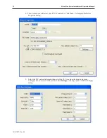
Page 247: ...he Add button will create a new worksheet to program a new macro The programmer first gives the macro a name in the top right corner Then programming can be added After the code is finished it needs compiled If the code compiles correctly there will be no errors and the macro name will be added to the top list If the macro does not compile correctly it will display error codes If the programmer sh...

Page 248: ...e macro was written a PLC Control Object was added where the Type of control was selected first to be Execute macro program Then the device type showed what bit types were available A LB was selected and the address 1 was entered Finally the macro name was selected Below shows the PLC control object attribute window 1010 1007 Rev 05 244 Silver Plus Series Installation Operation Manual PLC Object s...

Page 249: ...n be as many characters as you need to describe it the compiler has been tested to variable name lengths of 32 characters but it is best to keep the variable names small for ease of reading the code Variable names are not case sensitive so result is the same as ReSult or RESULT Variable names must always start with a letter i e variables cannot begin with a number or the underscore _ character Mem...

Page 250: ...ly seen within the function they are declared in Global variables retain their values and can be globally used by all functions Below are listed the various data types that can be declared TypeDescription Float Single Precision Floating point variable 32 bit signed IEEE 754 format Int Integer variable 32 bit signed Short Short integer variable 16 bit signed Char Character variable 8 bit unsigned B...

Page 251: ...racter constant ABCD char String 4 ABCD Boolean True not zero False zero True 1 False 0 bool Done 0 or bool Done False Reserved Words The following symbols and names are keywords that are reserved for use by macros They cannot be used as a complete name in any function name array name or variable name However the reserved words may be contained within a variable name such as my_int TheEnd etc And ...

Page 252: ...rator Bitwise operator is higher priority than a Comparison operator Logic operator is higher priority than an Assignment operator Main Functions and Sub functions The macro must have one and only one Macro_Command main function which is the execution start point of any macro file Any sub functions must be pre defined and written before the main function The format is Macro_Command main The main m...

Page 253: ...stElement table 0 LastElement table 99 Using Macros Within Recipes The macro utility can easily use the recipe memory area There are 65535 recipe word registers that are available to the user for general use addresses RW 0 to RW 65535 Register types RW RWI and the pointer LW 9000 can be used to read or write the recipe memory area RW registers are used to directly address a recipe register RWI reg...

Page 254: ...tyles of statements A declaration definition statement is constructed like the following Format Examples Explanation type name short MyVar This defines the name of the variable register and its type type name constant Short MyVars 10 This defines an array name and the constant is the number of type elements in the array An assignment statement will transfer assign an expression to a variable The f...

Page 255: ...ounter Step Options The increment decrement step of Counter It can be integer an can be omitted when value is 1 Statements Optional Statement block between For and Next which will be executed Format Examples For counter start To Down end Step steps Statements Next counter For n 100 Down 0 Step 3 n n 2 Next n For loop 0 To 20 Step 2 loop loop 1 2 Next loop While Wend statement Loop an unknown numbe...

Page 256: ...and The above example code defines a sub function called SQR This sub function allows one variable to be passed into it The function then takes the value passed to it multiplies its value by itself and then stores the result back into the same variable The result is returned back to the calling function Reading Writing External Registers in a Macro A macro program can communicate with external PLC...

Page 257: ... If the number of elements is more than 1 the DestVariable parameter must be declared as an array 1 16 100 SetData Function SetData DestData Addr_Type Address NumElements Description Writes data from a variable to a location in the PLC memory Parameter Description Example S DestData The name of the variable to retrieve the data from PLC Name The Name assigned to the controller in the device table ...

Page 258: ... the storage space in a macro PLC communication time may cause the macro to execute slower than expected Random macro compiler errors can often be corrected by recompiling again or canceling out of the macro editor and then reopen and compile again Some macros don t work the way they should due to the declaration of some variables and how they get interpreted Some Boolean arrays work better when d...

Page 259: ...nt is For variable initial value To end value Step Next variable Any format other than this format will cause compile error 22 While statement error missing While before Wend 23 Missing Wend statement The format of While statement is While logic expression Wend Any format other than this format will cause compile error 24 Illegal Break statement Break statement can only be used in For While or Sel...

Page 260: ...y_name constant constant is the size of the array Usage array_name integer character or constant Any format other than this format will cause compile error 40 Illegal Macro statement before declaration statement For example Macro_Command main int g 10 For g 2 0 To 2 g 3 4 g 9 int h k illegal definitions must occur before any statements or expressions Next g 2 End Macro_Command 41 Floating point ca...

Page 261: ...6 C Cable Routing and Noise Immunity 11 calibration 17 CE Compliance 7 change state 69 Circle tool using 116 Closing projects 64 Closing windows or screens 92 COM ports 25 Common windows above below the base screen feature 105 Common windows changing 107 Common windows using 104 Communications Settings 60 CompactFlash settings 22 CompactFlash transferring projects 23 Compiling 54 compress 65 compr...

Page 262: ...Graphics Object 3 Grid function 67 grid size 67 Group Libraries definition 132 Group Libraries deleting a group member 135 Grouping objects 73 H history 20 I increment key 43 Indirect Window Object 101 Installing the OIT 12 internal data memory 147 Internal OIT Memory 147 J Jog feature 162 JPG 121 K Keypad creating 185 Keypad displaying and using 186 L Labeling an object 155 languages 145 Language...

Page 263: ...Polygon tool using 117 Popup windows displaying 99 Port wiring 12 Power supply requirements 11 Programming the OIT wiring 15 Project 3 Project creating 35 ProjectManager 35 59 Projects Editing 62 Projects opening 62 Pulsing a bit using Set Bit Object 156 R Rectangle tool using 115 Redo command 70 Reserved local bits 150 reset button 17 Resizing a part or object 72 Rotation tools using 82 S Safety ...

Page 264: ...witch Object using 157 transfer settings 61 Trend Display Object using 197 U Underlay Windows assigning 96 assigning to a base window 97 how to display 97 rules that apply to 97 Undo command 70 USB jump drive 60 USB transferring projects 23 W WAV files 135 Window Copy 71 Window frames creating 97 Window Name 94 Window No Treebar using to navigate 66 Window definition of 3 Window deleting 98 Window...

Reviews: