background image


Powering up _____


Please read this instruction manual thoroughly before powering up your 

Stealth Max

 for 

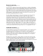
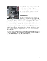
the first time. The location of the tubes on the driver board and chassis are shown below. 
When installing tubes, locate the key on the central spigot and make sure it matches with 
the indent on the tube socket. Push the tube into the socket with a slight rocking motion 
to ensure it seats properly. Removal is also easier of the tube is rocked slightly as it is 
pulled out. Don’t over-do the rocking as it can cause the spigot to break off. The KT88 
output tubes are installed as matched pairs as indicated on the boxes supplied with your 
amplifier. Matched quads are not required as individual bias controls are used for each 
channel. 
 
With the tubes installed, connect the IEC power cord to the AC input receptacle on the 
rear of the chassis. A proper sized fuse (3 A/250 V) has been installed (a spare is 
provided). Plug the cord into an ac outlet rated for at least 200 W (110-125 VAC or 230-
240 VAC for the export version, 50-60 Hz). The ac power switch is on the front panel. 
The red pilot light indicates the AC power is on. You will see the heaters light up, 
particularly in the KT88 tubes. It takes approximately 60 sec for the plate voltage to build 
up to the operational level and stabilize. This “soft start” maximizes the lifetime of the 
tubes and capacitors in your amplifier. 
 

Summary of Contents for Stealth Max

Page 1: ...loc Power Amplifier Users Manual Rev July 16 08 Mapletree Audio Design Lloyd Peppard R R 1 Seeley s Bay Ontario Canada K0H 2N0 613 387 3830 info mapletreeaudio com http www mapletreeaudio com Copyrigh...

Page 2: ...A431S used in the original Mk III amplifier The power transformer is conservatively rated and can deliver the current required for maximum power output Soft startup is assured through use of a 5AR4 GZ...

Page 3: ...hed pairs as indicated on the boxes supplied with your amplifier Matched quads are not required as individual bias controls are used for each channel With the tubes installed connect the IEC power cor...

Page 4: ...g conditions the meter reading should rise to around 1 Volt Adjust the bias potentiometer using a blade screwdriver counterclockwise CCW if the voltage is greater than 1 1 V and clockwise CW if the vo...

Page 5: ...SJ7GT can be substituted without change in performance The special red series 5693 can also be directly substituted and offers the potential for very long life 10 000 hrs No currently manufactured ver...

Page 6: ...ply ac Rated power output 4 8 50 W Frequency response at 1 W output 15 Hz 44 kHz 1 dB Frequency response at 50 W output 20 Hz 20 kHz 1 dB Gain 24 dB 16 V V or 1 2 V input for 50 W output Input resista...

Page 7: ...V5 GZ34 5AR4 6 3 VAC 6 A 200 mA 2 8 4 6 Y Y GR GR GR Y 60 R R BK R Y R BR BR chassis 10 Bias set 150K 150K 100 400 150K 150K 100 400 498 V 3 57K 117 0 047 400 511K 100K 20K 2 W 0 1 400 0 1 400 221K V...

Reviews: