background image

Menu

UTILITY

[

access by pushing the

UTILITY

button

]

From the  Default Screen

,

it is possible access the

UTILITY

menu pushing the

UTILITY

button

and the Sub-Menus pages can be selected just rotating clockwise and counter-clockwise the

NAV

/

PM1

encoder

.

Once selected the sub

-

menu page

,

using the 

ENTER

button can be accessed the Sub-Menus

pages

,

again 

scrollable

using the

NAV/PM1

encoder and accessible for the parameters

'

editing

pushing again the

ENTER

button

.

Through the 

ESC

button

,

it is any time possible to go back to the action and page preceding the

ENTER

button use

.

Once inside the Sub-Menus pages

,

the several options can be scrolled and using the PM2 or PM3

encoders and selected/confirmed pushing the

ENTER

button

.

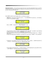
Note

:

In every Sub-Menu the option currently 

NOT  selected/running will have an 

asterisk


*

showing to the right of the description on the LCD screen

.

Options that are not selected/running will be displayed with Asterisk

.

Pushing the ENTER button on an unselected option will mean an asterisk will then appear and this
option will now take over as the currently selected/running option

.

System Utilities Sub-menu

 - this sub-menu allows to access several operations related to the

CLP2600 Start Up and General Configuration

:

From the 

System Utilities Sub-menu

,

pushing

ENTER

and then using the

NAV/PM1

encoder

for scrolling will give access to the following pages

:

Power-On Procedure

:

 this gives you the ability to select the option that will apply when the

CLP2600 powers up after being switched on

:

By pressing ENTER and rotating the

PM2

or 

PM3

encoder

,

it is possible to choose between

two options

:

Fade In On

or

Fade In Off

.

The currently running option will be displayed with an asterisk  to the right of the option
description

.

To change the option simply ENTER on the option not displaying the Asterisk and that option
will become active and an Asterisk will now appear to the right of the option description

.

The following two options are available

:

FADE-In

=

Off

. ..


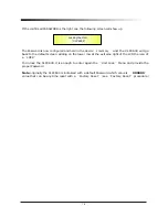
when the CLP2600 is turned on all Outputs regard of their status before the

Unit was switched off, will be MUTED or UNMUTED automatically

,

meaning the CLP2600 will

have no active Outputs or active Outputs

,

during the start-up process

,

depending from the

Outputs

'

previous status

.

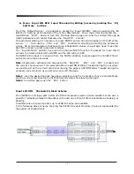
UTILITY MENU

:


System Utilities

SYSTEM UTILITY

:


Power

-

On Procedure

9

Summary of Contents for CLP-2600

Page 1: ...19 482mm DIGITAL USB...

Page 2: ...unit Refer all servicing to qualified service personnel To prevent the risk of shock do not attempt to service this equipment yourself because opening or removing covers may expose you to dangerous vo...

Page 3: ...ibility to store recall up to 20 presets but is coming with no factory presets After the initialization the CLP2600 will show on the LCD the current preset if any available otherwise if no presets ava...

Page 4: ...two seconds Input Channels LIN or RIN are either muted or unmuted The red LED will illuminate when the Channel is muted When the MUTE LED is OFF then the related Input Channel is UN MUTED A momentary...

Page 5: ...0 2 UTILITY MENU Program Utilities 2 1 PROGRAM UTILITY Recall a Program Recall a Program 01 Preset 01 24 Preset 24 2 2 PROGRAM UTILITY Save a Program Save a Program 01 Preset 01 24 Preset 24 2 3 PROG...

Page 6: ...n selected a Bell filter just defining its Bandwidth BW to be greater then 0 then the Bell filters can be set by the following parameters 3 1 Output A B Left Right EQ X up to 5 filters available 1 00k...

Page 7: ...f On 3 Output A B Left Right AGC AGC Exp Time 1 500S AGC Exp Time 1 500S PM1 N A PM2 N A 0 057S 14 400S 4 Output A B Left Right AGC AGC Cmp Time 0 500S AGC Cmp Time 0 500S PM1 N A PM2 N A 0 014S 6 000...

Page 8: ...mp Rto 4 1 PM1 N A PM2 N A 1 1 16 1 10 Output A B Left Right Delay Delay 0 000 ms Delay 0 000 ms PM1 N A 000 0000mS 000 0000mS 1 ms steps 20 8 us steps 848 0000mS 000 9984mS 11 Output A B Left Right P...

Page 9: ...if selected the number of bands in the editing environment of the Compressor 1 the choice will be replicated on the editing environments of the Compressors 2 3 So if selected the Monoband Compressor f...

Page 10: ...shold 3dBu Threshold 3dBu PM1 N A PM2 N A 8dBu 20dBu 7 Output A B Left Right Cmp1 Ratio 2 1 Ratio 2 1 PM1 N A PM2 N A 1 1 32 1 8 Output A B Left Right Cmp1 Knee Soft Hard 0 Knee Soft Hard 0 PM1 N A PM...

Page 11: ...er as the currently selected running option System Utilities Sub menu this sub menu allows to access several operations related to the CLP2600 Start Up and General Configuration From the System Utilit...

Page 12: ...ement is Time milliseconds Input Routing the CLP2600 Processor is equipped with 2 Analog Inputs Balanced Female XLR and a stereo S PDIF Digital Input RCA connector The Routing Options page allows you...

Page 13: ...the following If presets have previously been stored by the user anyone of them can be recalled By using the PM3 encoder it is possible to scroll through the stored presets Once the desired preset app...

Page 14: ...page the User can enter a Preset Name up to 16 Characters by using the PM3 encoder to choose a character and the NAV PM1 encoder to move between the 16 available locations for the character s positio...

Page 15: ...y time it is possible to quit the storing action by pressing the ESC button Delete a Program this page allows you to delete a preset already stored in the CLP2600 memory By pressing the ENTER button a...

Page 16: ...ote control interface USB or RS485 to be used for controlling the CLP2600 From Interface Utilities press ENTER to access the Interface Setup Interface Setup this screen allows you to choose the remote...

Page 17: ...r to move between available locations you can enter a 6 Character Password Name The current position of the cursor for the characters to be entered is shown by a blinking underscore During this editin...

Page 18: ...t screen adding on the lower row at the extreme right of the LCD the icon of a LOCK To Unlock the CLP2600 it is enough to enter again the Unit Lock Menu and provide the proper Password Note originally...

Page 19: ...UTE the input it is enough from the MUTE condition to press again the Eq Edit Mute button for more than 3 seconds Note All parameter editing can be done using the NAV PM1 PM2 and PM3 encoders and the...

Page 20: ...el Filter 12dB Oct Slope Butwrth 18dB Butterworth Filter 18dB Oct Slope Butwrth 24dB Butterworth Filter 24dB Oct Slope Lnk Ril 24dB Linkwitz Riley Filter 24dB Oct Slope Bessel 24dB Bessel Filter 24dB...

Page 21: ...e it is necessary to have the filter s GAIN 0 0dB then using the PM2 encoder rotate it clockwise in order to decide the Peaking filter s Bandwidth or counter clockwise to select the Shelving filter ty...

Page 22: ...Center Frequency of the Parametric Filter can be edited using the NAV PM1 encoder the BW the PM2 encoder and the Gain the PM3 encoder Center Frequency the selectable frequencies range is from 20Hz to...

Page 23: ...PM1 encoder Note Once the desired High Shelving filter is selected the PM3 can then be used to select the desired GAIN and when the GAIN is set at a value different from 0 0dB then the filter type can...

Page 24: ...from the BYPASSED condition to press again the Lim Comp Edit Bypass button for more than 3 seconds Note All parameter editing can be done using the NAV PM1 PM2 and PM3 encoders and the current shown v...

Page 25: ...on level when the averaged signal is beyond a defined Threshold Thr Hold The AGC implemented in the CLP2600 is acting on the evaluation of an input signal which is ana averaged one on a 50ms time fram...

Page 26: ...ress ENTER an arrow will appear on the left of the screen then use the PM3 encoder The following is an example screen for the AGC Bypass page where the AGC is set Active AGC Exp Time page from this sc...

Page 27: ...t not higher than 1 If the Expansion Ratio is set to 2 the signal can be expanded up to a max amplitude that is twice the original one The following is an example screen for the AGC Exp Ratio page whe...

Page 28: ...here the Polarity of Output Channel 1 is set to Normal Peak Limiter sub menu from this page it is possible to set the Output Channels Peak Limiter The following is an example screen for the Peak Limit...

Page 29: ...the PM3 encoder Note The Peak limiter Threshold is defined in Vp due to the fact that with both Sinusoid and Squared wave testing signals the CLP2600 Peak Limited output Vp Peak Peak Level is the sam...

Page 30: ...gain the Lim Comp Edit Bypass button for more than 3 seconds Note All parameter editing can be done using the NAV PM1 PM2 and PM3 encoders and the current shown value of the selected option is AUTOMAT...

Page 31: ...he 2 bands The buttons order is set so to be the number one the button locate at the most far left position from the LCOMP RCOMP labels Band Mode page from this page it is possible to set CLP2600 way...

Page 32: ...d on the CrossOver 2 editing page The following is an example screen for the CrossOver 1 page where theCross Over frequency is set to 250Hz CrossOver 2 page when the CLP2600 is set in Mono Mode 1 band...

Page 33: ...the input signal itself so to make more Musical the Compressors action The RMS Compressor it is so maintaining constant the output energy and not the Output peak so to have for the different inputs in...

Page 34: ...Time the selectable range of the RMS Compressor s Release Time is from 0 1s to 3s in steps of 0 1s Threshold page from this page it is possible to set the T hreshold parameters of the RMS Compressor O...

Page 35: ...ompressor s Knee editing page can be entered and using the PM3 encoder the Ratio parameter can be set Drive the selectable range of the RMS Compressor s Drive is from 12dB up to 6dB by steps of 0 5dB...

Page 36: ...bar of led meters is showing when turned on the Lim led that the Peak Limiter is active and limiting the output signal with the Clip led an occurring Clip on the output signal and with the other leds...

Page 37: ...evel 20dBu Analog Output Signal Ch1 Ch2 Bal Male XLR Maximum Output Level 20dBu Digital Processing DSP SAM3716 24bits data x 96 bits coeff A D Converters AKM5392 24bits D A Converters AKM4396 24bits S...

Page 38: ...Http www marani com cn MAINS...

Reviews: