background image

Summary of Contents for 105B

Page 1: ...SERVICE MANUAL ...

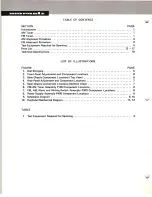
Page 2: ...t Panel Adjustments and Component Locations 6 3 Main Chassis Component Locations Top View 6 4 Rear Panel Adjustment and Component Locations 7 5 Main Chassis Component Locations Bottom View 7 6 FM AM Tuner Assembly P100 Component Locations 8 7 FM AM Mono and Muting Switch Assembly P300 Component Locations 8 8 Power Supply Assembly P400 Component Locations 8 9 Schematic Diagram 9 10 10 Exploded Mech...

Page 3: ... output is obtained from pin terminal J118 and applied to the output jacks th rough the f unct ion switch The DC com ponent of the det ected IF signal is used as a AGC voltage to control emitter current of H 104 through the resistor R185 A part of IF signal output is also applied to the diode H124 through a capacitor C1BO and rect if ied to obtain DC current for energizing the AM signal strengt h ...

Page 4: ... CD on the MPX decoder IC Hl14 The MPX decoder Ie consists of a stereo decoder and postampl ifier for the output The right and left channel signals decoded by the stereo decoder H11 4 appear at pin right channel and pin QJ left channel respectively These signals are passed through the low pass filters and de emphasis networks to eliminate undesirable residual switching signals and are then deliver...

Page 5: ...output as necessary to avoid AGC action 4 FMAlignment Procedure 1 Connect a FM signal generator to the FM antenna terminals and a oscilloscope and an audio distortion analyzer to the tape output jacks on the rear panel 2 Set the FIVI SG to 87 5 MHz and provide about 3 to 5 J lV Place the tuning pointer at the low frequency end by rotating the tuning knob and adjust the core of oscillator coil L 10...

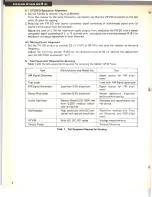
Page 6: ...istor R153 for the threshold level of 25 lV during this adjustment turn the MUTING pushswitch on 5 Test Equipment Required for Servicing Table 1 lists the test equipment required for servicing the Model 105 B Tuner Item Manufacturer and Model No Use AM Signal Generator Signal source for AM align ment Test Loop Used with AM Signal generator I FM Signal Generator Less than 0 3 distortion Signal sour...

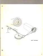
Page 7: ...56 POINTER Figure 1 Dial Stringing 5 ...

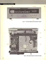
Page 8: ... A _C wnod I ion SOOl Figure 2 Front Panel Adjustments and Component Locations 1 P400 l02 Figure 3 Main Chassis Component Locations Top View 6 ...

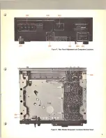
Page 9: ...JO 3 LOOt J012 Figure 4 Rear Panel Adjustment and Component locations GOOt ROOl o 1 61 Figure 5 Main Chassis Component locations Bottom View 7 ...

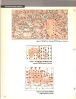
Page 10: ... Figure 6 FM AM Tuner Assembly Pl00 Component Locations Figure 7 FM AM Mono and Muting Switch Assembly PlOO Component Locations IVV ee _ I W1I Figure 8 Power Supply Assembly P400 Component Locations 8 ...

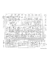
Page 11: ...H 113 ti1l4 H l5 116 ll 9 IZ5 H H 7 118 TRANSISTOR HD2001105 HTl05361G HTl05361 E COf HU cTION 2SC536G 2SC536E 151555 IBOTTOM VIEW I M HIO AM HIOZ_t nI3 LOCH O ORAIN z S SOURCE G GATE E EMITTER MOOI COOl fiflure 9 Schematic 1 1401 ...

Page 12: ......

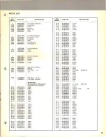
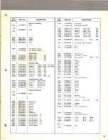
Page 13: ...0510214 lKn R123 RT0510114 loon R124 RT0515114 150n R125 RT0533114 330n REF DESIG PART NO DESCRIPTION R126 R127 R128 R129 R130 RT0533214 RT0510214 RT0533214 RT0515314 RT0527214 3 3Kn lKn 3 3Kn 15Kn 2 7Kn R131 R132 R133 Rl34 R135 R136 R137 Rl38 R139 R140 RT0515114 RT0533114 RT0515114 RT0510114 RT0510414 RT0515114 RT0582214 RT0515314 RT0510214 RT0522114 150n 330n 150n lOOn 100Kn 150n 8 2Kn 15Kn lKn ...

Page 14: ... 161 0201 Film O OOl uF 10 C152 EA1060169 Electroly 1O uF 16V C153 EA3360109 Electroly 33 uF 10V REF PART NO DESCRIPTION DESIG C154 OF1627201 Film 0 0027 uF 10 C155 OF1627201 Film 0 0027 uF 10 C156 EA4740501 Electroly OA7 uF 50V C157 EA4740501 Electroly OA7 uF 50V C158 OFl647201 Film 0 0D47 uF 10 C159 OFl647201 Film 0 0047 uF 10 C160 OF1533205 Film 0 0033 u F 5 C161 OF1533205 Film 0 0033 uF 5 C162...

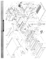
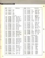
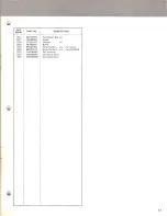
Page 15: ...icker Bearing Spacer Bracket K F H M Screw x 2 B H M Screw x4 B H M Screw x4 B H M Screw x6 B H M Screw x2 B H M Screw x3 B H M Screw P300 R301 R302 R303 R304 R305 R306 C301 S301 J301 J302 Sool MOOl COOl 0417 1438 1439 0501 0503 0505 0502 1436 1437 0414 0631 J005 J006 J007 J008 M002 MOO3 MOO4 M005 1537 1538 R003 0415 0518 1536 P200 M201 M202 M203 J201 I J205 I YD2849OO3 ZZ2849703 RT0510214 RT05102...

Page 16: ...rew x2 0219 951091101 Label LL NO For CANADA 0807 54050300R T L Washer OR x2 0220 282186102 Label Caution For CANADA 0808 53110303E Hexagon Nut x 2 0224 951110103 Label UL For U S A 0810 51100310S B H M Screw x2 0225 245786104 Label CSA For CANADA 0811 53110303E Hexagon Nut x 2 3037 951091102 Label For U S A ROOl GT0522512 Resistor 2 2Mn 5 hW 0302 51122608E T H M Screw x4 0304 51100406S B H M Scre...

Page 17: ...4 1332 1333 1334 901302501 102980401 273182101 281905601 952281501 952301512 ZA0200007 Z00200010 Z00120006 I Polyethylen Bag x 2 Sleeve Silicagel x2 Buffer Serial No Card x4 For U S A Serial No Card x 4 For CANADA Ext Antenna Connective Cord Connective Cord 17 ...

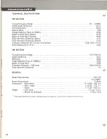
Page 18: ...paration at 1KHz 40dB AM SECTION Tuning Frequency Range 540 1 605K Hz Usable Sensitivity _ 2511 V Selectivity 20dB Image Rejection Ratio at 1400KHz 40dB Signal to Noise Ratio 45dB Frequency Response 3dB down 50Hz 3 3KHz Total Harmonic Distortion 1 GENERAL Power Requirements 120 V AC 50 to 60 Hz Power Consumption __ _ _ 15 Watts Dimensions Panel Width 14 11 64 360 mm Panel Height _ 4 23 32 120 mm D...

Page 19: ... 7l iii MARANTZ CO INC P O BOX 99 SUN VALLEY CALIFORNIA 91352 A WHOllY OWNED SUBSIDIARY OF SUPERSCOPE INC SUN VAllEY CALIFORNIA 91352 284985504 0 ...

Reviews: