15
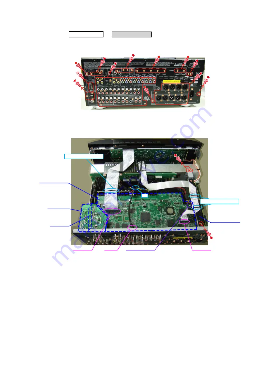
4. HDMI UNIT ASSY
(1) Remove the screws, then remove the BACK PANEL and the HDMI BRACKET.
(2)
Cut wire clamp band, then disconnect the connector wires and the FFC cables. Remove the screws and the
SUPPORT PWB.
Remove the PCB SIRIUS and the PCB RS232 from the PCB SIDE CNT(Board to board).
CABINET TOP
HDMI UNIT ASSY
→
Proceeding :
Direction of photograph: A
U model
STYLE
PIN : Loose
STYLE
PIN : Loose
FFC cable
cut
HDMI BRACKET
SUPPORT P.W.B.
HDMI UNIT ASSY
SIRIUS UNIT
232C UNIT
N4201
FFC cable
Summary of Contents for AV7005/N1B
Page 62: ...62 Personal notes ...
Page 64: ...64 BLOCK DIAGRAM ...
Page 139: ...139 R5F3650KNFB HDMI U5500 ...
Page 146: ...146 IS42S32200E6TL HDMI U1602 IS42S32200E6TL Block diagram ...
Page 155: ...155 AK4424ET HDMI U3800 U3801 AK4424ET Block Diagram ...
Page 156: ...156 AK5358BET HDMI U3802 AK5358BET Pin Function ...
Page 160: ...160 HY27UF081G2A TPCB Block Diagram ...
Page 170: ...170 2 FL DISPLAY FLD 19 ST 02GINK FRONT Z1001 PIN CONNECTION GRID ASSIGNMENT ...
Page 171: ...171 ANODE CONNECTION ...
Page 172: ...172 VFD GP1261AI FRONT Z1002 PIN CONNECTION PATTERN DETAIL ...


