3-1
3-1
DISMANTLING INSTRUCTIONS
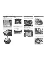
Dismantling of the Tray Assembly and Servo board
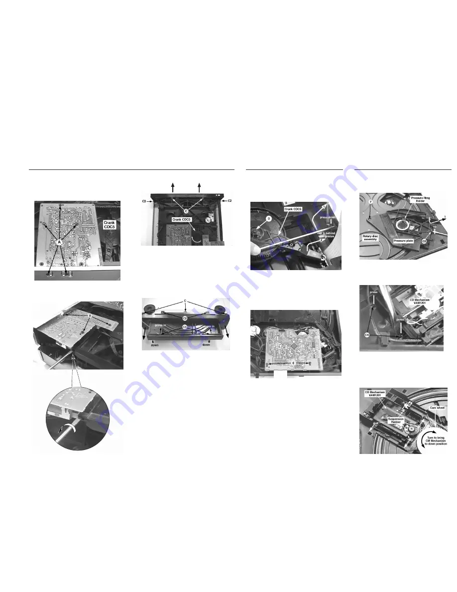
1) Remove the Metal rod (pos 152) as indicated.
2) Loosen the Crank CDC5 (pos 96) with screw D and lift the
crank arm out of the groove on the tray assembly. The
complete tray assembly can be pulled out of the Frame
(pos93).
3) Remove the Servo board by 2 screws E.
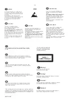
4) Protect the CD mechanism's Laser against ESD by short-
circuiting the flexfoil with a paper clip immediately upon
disconnection from the flexfoil connector.
(See Warning for more details)
Dismantling of the CD Mechanism
1) Loosen the Pressure ring holder (pos 90) by relasing catch
C3 as indicated.
2) Remove the Pressure plate (pos 89) and Rotary disc
assembly (pos 100) by 1 screw F.
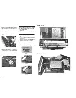
3) Turn the Tray assembly upside-down and remove the
CDM Lock (pos 99) by using a "minus" screw-driver to
release 2 catches C4 as indicated.
4) With the Tray assembly facing up again, turn the cam
wheel (pos 116) to bring the CD mechanism (pos 98) to the
down position. Remove the CD mechanism by sliding out
the 4 rubber suspension (pos 104 to 107).
Dismantling of the DAC/AF board, Supply board and Front Panel Assembly
1) Remove the Top Cover (pos 151) by 8 screws.
- 2 screws on each side
- 4 screws from the rear
2) Remove the DAC/AF board by 5 screws A. Be careful not
to damage flex cable.
3) Remove the Supply board by 3 screws B and disconnect
the Lever Power button (pos 6) as indicated.
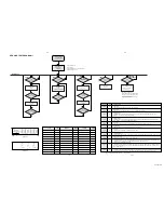
5) With the set upside-down, release the 2 catches C1 and
remove the tray cover as indicated.
6) Loosen the Front Panel assembly from the bottom bracket
(pos 181) by 5 screws C and 4 catches C2 as indicated.
- 2 screws on top
- 3 screws from the bottom side
4) Turn the crank CDC5 (pos 96) clockwise to slide out the
tray assembly.
Turn
Tray moves out
PCS 101 015


