3-2
3-2
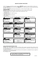
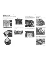
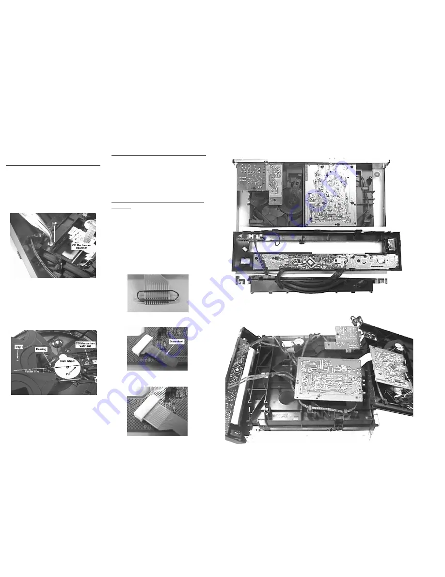
Assembly of the CD mechanism and Rotary disc CDC5
1) Remove the 4 rubber suspension (pos 104-107) from the
Support bracket (pos 114) and attached them on to the
CD mechanism.
2) Place the CD mechanism with the rubber suspension
above the mounting 4 holes.
3) Hold the CD mechanism in position and pull the tips of the
rubber suspension through the holes in the Support
bracket.
4) After assembly of the CD Mechanism, the Cam wheel (pos
116) and the Rotary disc (pos 100) must be re-aligned.
This is done by positioning the Bearing (pos 101), pin on
the Cam wheel and CD Mechanism in a straight line as
indicated.
5) Assemble the Rotary disc onto the Bearing with the "1"
printing mark facing the CD Mechanism.
Warning
Charged capacitors on the Servo board may damage the
CD drive electronics when connecting a new CD mecha-
nism. That's why, besides the safety measures like
* Switch off power supply
* ESD protection
Additional actions must be taken by the repair techni-
cian.
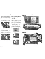
The following steps have to be done when replacing the CD
Mechanism:
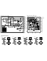
1) Disconnect the old CD mechanism flexfoil from printed
board.
2) Connect paperclip to CD mechanism flexfoil to short-
circuit flexfoil (fig.1).
3) Short-circuit printed board with brass-sheet (4822 321
11197) plugged into the flexfoil connector (fig. 2).
4) Remove the old CD mechanism.
5) Assemble the new CD mechanism into position.
5) Remove short-circuit from printed board connector.
6) Remove short-circuit from flexfoil of new CD mechanism.
7) Connect new flexfoil to print connector (fig. 3).
Figure 3
Figure 2
Figure 1
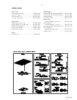
SERVICE POSITION 2
SERVICE POSITION 1
PCS 101 016


