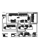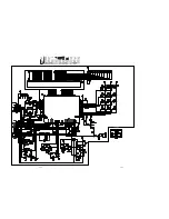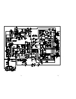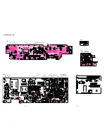
1-11
8-4 AS Adjustment
CAUTION :
Do not see the laser pick-up! Cover the laser pick-up unit
while AS adjustment.
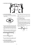
Adjustment point : VR120, VR121
Test point : TP107(+), TP120 (+) TP105 (GND)
Equipment : Digital Multi Meter (DC voltage)
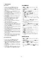
1. Press the mains switch (
POWER
BUTTON) while depressing
the
PLAY
button and
STOP
button.
2. Status will be on the
TEST mode 2
and FL display shows
<
TEST 2
>. After a couple of seconds FL display shows
<
TEST2 OK
>.
3. Press the
button. Then the FL display shows <
E3 02
>
and the status will be in
AS adjustment mode
.
4. Measure the DC voltage at the test point
TP107
.
5. Press the
button again. Then the DVD laser will light ON
and the FL display shows <
E3 00
>.
6. Press the
button again. Then the CD laser will light ON
and the FL display shows <
E3 01
>.
7. Adjust the voltage at the test point
TP120
by
VR121
, that the
value must be same as
TP107
(10mV) value measured on
#4. process.
8. Press the
button twice of time. Then the DVD laser will
light ON and the FL display shows <
E3 00
>.
9. Measure the DC voltage at the status
DVD laser light ON
.
Adjust the voltage at that status 35mV (±10mV) lower than
“CD laser light ON “ status by the trim resister VR120.
10.Press the
button again. Confirm the DC voltage at the
status
CD laser light ON
.
(DC voltage must be 35mV higher than the status
DVD
laser light ON
.)
11.Power OFF the mains switch (
POWER
BUTTON).
Summary of Contents for DV7000
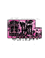
Page 15: ...1 13 1 14 1 10 WARNINGS ...
Page 16: ...1 15 1 16 1 11 BLOCK DIAGRAM ...
Page 17: ...1 17 1 18 1 12 SCHEMATIC DIAGRAM AND PARTS LOCATION ...
Page 18: ...1 19 1 20 ...
Page 21: ...1 25 1 26 ...
Page 36: ......
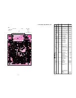
Page 37: ...2 1 2 2 Not for DV4000 2 1 SCHEMATIC DIAGRAM AND PARTS LOCATION ...
Page 38: ...2 3 2 4 ...
Page 39: ...2 5 2 6 Not for DV4000 ...
Page 42: ...2 11 2 12 ...
Page 48: ...2 20 MN66261 CD signal processing ...
Page 49: ...2 21 MN66261 CD signal processing ...
Page 50: ...2 22 MN67700 Servo processing IC ...
Page 51: ...2 23 MN67700 Servo processing IC ...
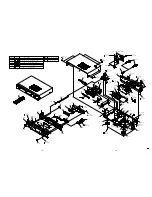
Page 56: ...2 28 2 3 EXPLODED VIEW AND PARTS LIST TKM1000MZ ...


