2-25
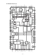
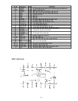
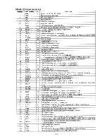
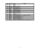
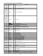
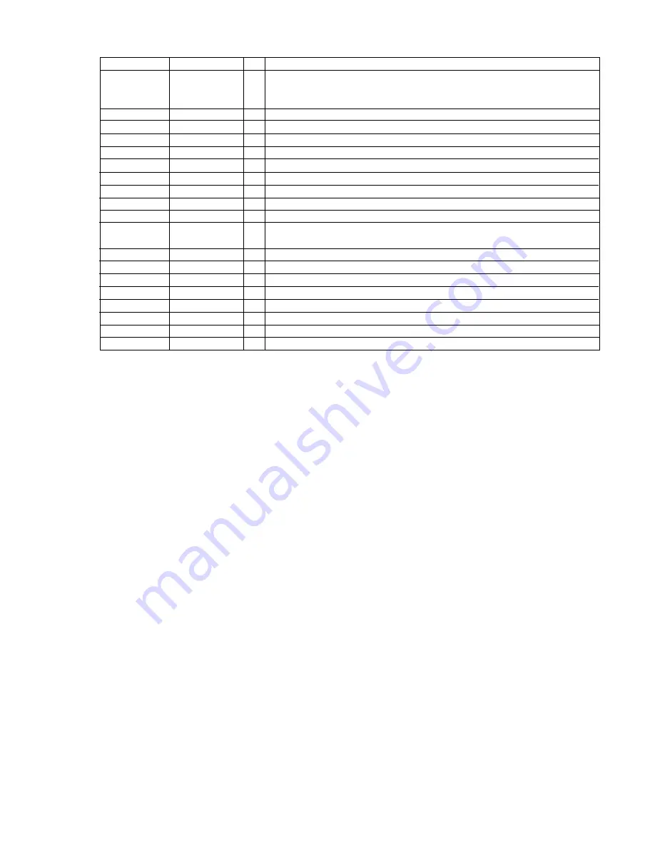
Pin No.
Port Name
I/O
FUNCTION
127-130
133-139
CPUADT0-15
I/O
CPU address/data bus.
143-147
141
XRESET
I
Global reset input.
148-152
CPUADT16-20
I
CPU address bus.
153
XALE
I
Address latch enable input.
154
XRE
I
Read strobe.
155
XINTO
O
ECC interrupt request.
158
XWEH
I
Write strobe signal.
159
XWAIT
O
CPU wait state control.
168
XHSTCS
O
Decipher chip select.
176
STENABLE
I
Stream data request.
177-181
STD0-7
O
Output stream data bus.
185-187
183
GENCLK
I
27 MHz clock input.
188
STCLK
O
Output stream data transfer clock, falling edge active, 6.75 MHz.
189
STVALID
O
Output stream data valid.
190
XVCS
O
Latched video decoder chip select.
191
XVDS
O
CPU read/write strobe.
192
HRXW
O
CPU write strobe, XWEH
193
ASCK
O
Latched audio decoder chip select.
207
SELCPU
I
1: data corresponds to CPUADT15-8. 0: data corresponds to CPUADT7-0.
Summary of Contents for DV7000
Page 15: ...1 13 1 14 1 10 WARNINGS ...
Page 16: ...1 15 1 16 1 11 BLOCK DIAGRAM ...
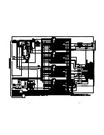
Page 17: ...1 17 1 18 1 12 SCHEMATIC DIAGRAM AND PARTS LOCATION ...
Page 18: ...1 19 1 20 ...
Page 21: ...1 25 1 26 ...
Page 36: ......
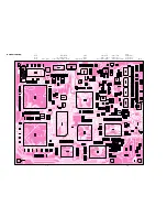
Page 37: ...2 1 2 2 Not for DV4000 2 1 SCHEMATIC DIAGRAM AND PARTS LOCATION ...
Page 38: ...2 3 2 4 ...
Page 39: ...2 5 2 6 Not for DV4000 ...
Page 42: ...2 11 2 12 ...
Page 48: ...2 20 MN66261 CD signal processing ...
Page 49: ...2 21 MN66261 CD signal processing ...
Page 50: ...2 22 MN67700 Servo processing IC ...
Page 51: ...2 23 MN67700 Servo processing IC ...
Page 56: ...2 28 2 3 EXPLODED VIEW AND PARTS LIST TKM1000MZ ...

