1-6
STOPPER TUB
6-1. Removal of the TRAVERSE MECHA.
6-1-1. Removal of the MECHANISM BLOCK
1) Turn the unit
'
s power on and press the "EJECT" button to
eject the DISC TRAY.
2) Disconnect the power cord and remove the DISC CLAMPER
BLOCK.
3) Completely remove the DISC TRAY by pulling it outwards
while pulling up both of the stopper tabs alternately.
Fig. 6-1
4) Disconnect the two flat cables from the P803 connectors
and one flat cable from the P808 connector on the MAIN
PCB.
5) Disconnect the P807 connector on the MAIN PCB.
6) Remove the four a retaining screws and remove the
MECHANISM BLOCK from the chassis.
Fig. 6-2
A SCREW
6. REPLACEMENT OF PRINCIPAL COMPONENTS
6-1-2. Removal of the TRAVERSE MECHA.
1) Remove the four b screws on the MAIN PCB and then
disconnect the P800 connector on the MAIN PCB.
Fig. 6-3
2) Short the laser diode protection circuit on the PICK UP
BLOCKÕs flexible cable with solder as shown.
Caution
To protect the laser diode from damage caused by high voltage
static electricity, a laser diode protection circuit has to be
shorted before disconnecting the flexible cable (P200 connector
on the MECHANISM PCB). It is recommended that you put
solder on the top of the soldering iron as shown in Fig. 3-5
then short the circuit at once. When you replace the TRAVERSE
MECHA., be sure to connect the P200 connector before
removing the solder at the shorted parts.
B SCREW
P200
SOLDER
Fig. 6-4
Fig. 6-5
Summary of Contents for DV7000
Page 15: ...1 13 1 14 1 10 WARNINGS ...
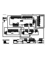
Page 16: ...1 15 1 16 1 11 BLOCK DIAGRAM ...
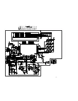
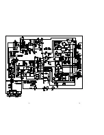
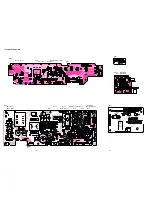
Page 17: ...1 17 1 18 1 12 SCHEMATIC DIAGRAM AND PARTS LOCATION ...
Page 18: ...1 19 1 20 ...
Page 21: ...1 25 1 26 ...
Page 36: ......
Page 37: ...2 1 2 2 Not for DV4000 2 1 SCHEMATIC DIAGRAM AND PARTS LOCATION ...
Page 38: ...2 3 2 4 ...
Page 39: ...2 5 2 6 Not for DV4000 ...
Page 42: ...2 11 2 12 ...
Page 48: ...2 20 MN66261 CD signal processing ...
Page 49: ...2 21 MN66261 CD signal processing ...
Page 50: ...2 22 MN67700 Servo processing IC ...
Page 51: ...2 23 MN67700 Servo processing IC ...
Page 56: ...2 28 2 3 EXPLODED VIEW AND PARTS LIST TKM1000MZ ...


