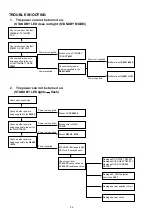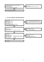
TROUBLE SHOOTING
1. The power can not be turned on.
(STANDBY LED does not light (STANDBY MODE))
2. The power can not be turned on.
(STANDBY LED lights
flash)
Check insertion of the
8U-
110160-4/-7
STANDBY
PCB.
Check insertion of the
8U-
310151
U-COM UNIT.
Check whether power is
being supplied to the coil
of the STANDBY TRANS
T8501
.
Broken wire in STANDBY
TRANS
T8501
.
Malfunction of
D8501-8506.
Check whether power
is being supplied to the
D8501-8506
.
Malfunction of
U8501
,
U101
.
Power not supplied.
Power supplied.
Power not supplied.
Power supplied.
Check whether power is
being supplied to the
F8520
.
Check each connector.
Check whether power is
being supplied to the coil of
the MAIN TRANS.
Check whether power is
being supplied to the
D8509
- 8518
.
Broken
D8509 - 8518
.
Broken wire in MAIN
TRANS.
Broken FUSE
F8520
.
Damaged P_DWN detection
circuit and
U101
.
Damaged DC OFFSET DETECT.
Damaged OVER HEAT DETECT.
Damaged OVER CURRENT
DETECT.
STANDBY LED repeats ON/
OFF for 0.5 seconds each.
Damaged power amplifier circuit
Damaged power circuit.
Power not supplied.
Power not supplied.
Power not supplied.
Power supplied.
Check input level,
SPEAKER connection and
SPEAKER resistance value.
32
Summary of Contents for Icemaker
Page 8: ...Personal notes 8...
Page 27: ...10 Click the E P R 11 Click the OK 27...
Page 39: ...Personal notes 39...
Page 43: ...WIRING DIAGRAM 43...
Page 65: ...TC7WHU04FU DIGITAL U301 U303 U804 U805 65...
Page 66: ...PCM9211 DIGITAL U302 PCM9211 Block Diagram 66...
Page 67: ...PCM9211 Pin Discriptions 67...
Page 71: ...CS2000 CP DIGITAL U801 CS2000 CP DIGITAL U3914 Block Diagram 71...


