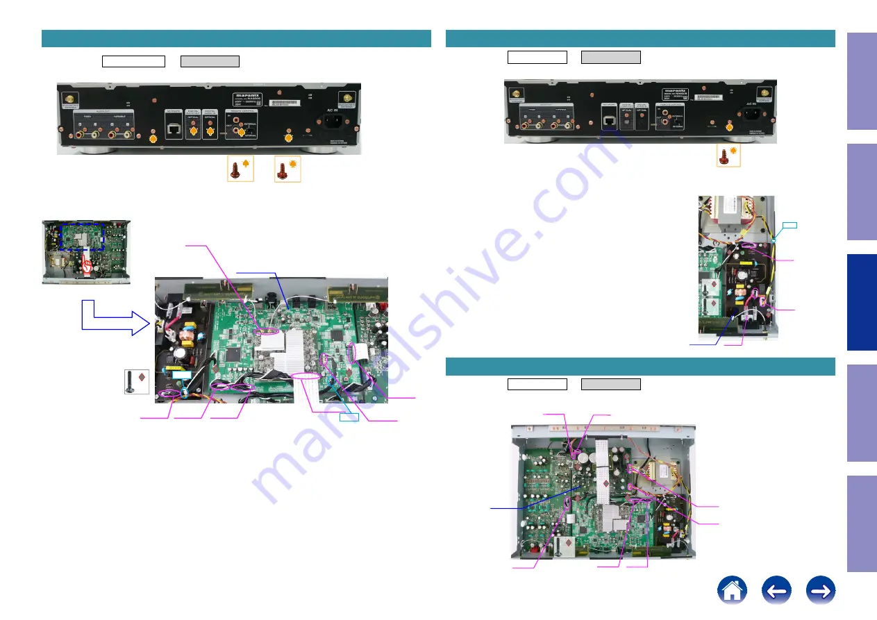
Proceeding :
TOP COVER
→
MAIN PCB
(1) Remove the screws.
(2) Remove the screws. Remove the connector wire and FFC.
2. MAIN PCB
x2
x3
x2
MAIN PCB
Antenna
connector
CN3002
CN3003
CN3006
Loosen
CN3000
CN3009
Cut
CN441
Proceeding :
TOP COVER
→
SMPS PCB
(1) Remove the screws.
(2) Remove the screws. Remove the connector wire and FFC.
Proceeding :
TOP COVER
→
POWER PCB
(1) Remove the screws. Remove the connector wire and FFC.
3. SMPS PCB
x1
SMPS PCB
x2
x2
CN801
CN802
CN441
Cut
4. POWER PCB
POWER PCB
CN2000
CP1004
CN3001 CN3000
CP1000
CP1001
CP1002
x4
Before Servicing
This Unit
Electrical
Mechanical
Repair Information
Updating
37


