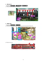
1. FRONT PANEL ASSY
Proceeding :
TOP COVER
→
FRONT PANEL ASSY
(1) Remove the screws.
(2) Cut the wire clamp, then remove the connector wires and FFC. Remove the Style pin and screws.
(3) Remove the screws.
View from the bottom
Front side
FFC
FFC
N7005
N7002
CP4401
CUT
STYLE
PIN
Shooting direction: D
Shooting direction: C
13
Summary of Contents for NR1605/FB
Page 8: ...Personal notes 8 ...
Page 26: ...Personal notes 26 ...
Page 103: ...CX870 7P 8P 5P PLATE PLATE 2P 7P 4P 7P 11P 5P 8P PLATE S30SC6MT WIRING DIAGRAM 103 ...
Page 140: ...Personal notes Personal notes 140 ...
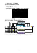
Page 161: ...2 FL DISPLAY FLD 018BT021GINK FRONT U4400 PIN CONNECTION GRID ASSIGNMENT q T7 161 ...
Page 162: ...ANODE CONNECTION 162 ...


