background image

33

FUNCTION .............

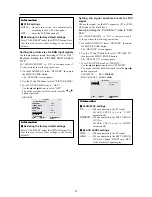
Set the LONG LIFE function.

 To reset the program

Align the cursor with the DATE field that you wish to
reset, then press the CLEAR button.

 To reset the data

Align the cursor with the field (ON/OFF/INPUT/
FUNCTION) that you wish to reset, then press the
CLEAR button.

 Special characters in the PROGRAM TIMER

screen

PROGRAM TIMER

EXIT

DATE

MON

TUE

SAT

*

FRI

SAT

*

SEL.

RETURN

ADJ.

ZOOM

ON

08 : 30

- - : - -


08 : 30

08 : 30

- - : - -


08 : 30

15 : 30

OFF

10 : 30

18 : 15

12 : 15

10 : 00

- - : - -


12 : 15

16 : 00

INPUT

RGB2

VIDEO1

HD/DVD1

VIDEO1

RGB1

FUNCTION

INVERSE

WHITE

WHITE

• An asterisk “

*

” in the DATE field

An asterisk “*” means “every”. For example, “*FRI”
means every Friday and “*” means everyday.

• A hyphen “

-

” in the ON field or OFF field

If any hyphen remains in the ON field or OFF field, the
FUNCTION can not be set.

• A hyphen “

-

” in the FUNCTION field

A hyphen “-” means last mode (the mode that was last
selected at the time the power was switched off).

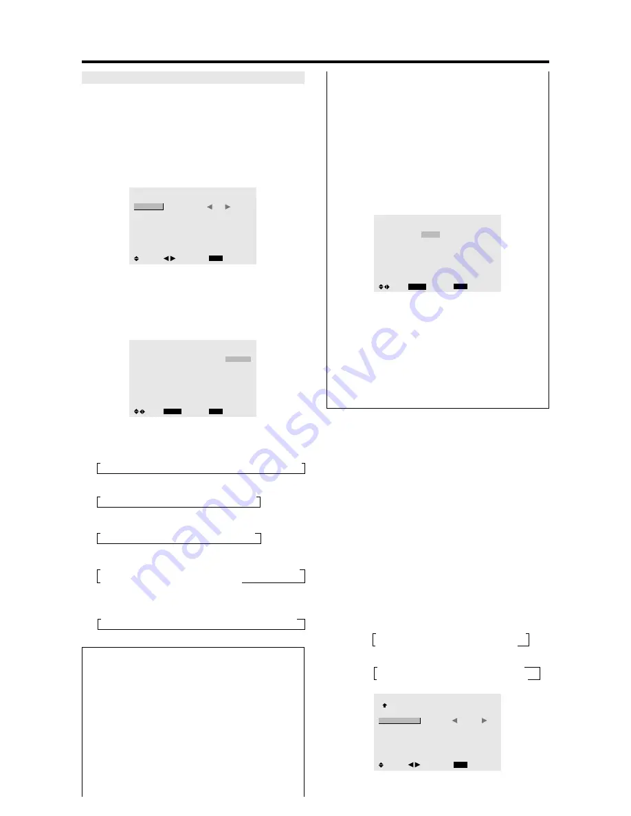
Setting the power on mode

This function sets the input mode at the time the power is
switched on.

Example: Setting “VIDEO2”

Set “ADVANCED OSM” to “ON” in the main menu (1/
2), then perform the following operations.

1. On the MAIN MENU, select “OPTION3”, then press

the MENU/ENTER button.
The “OPTION3” screen appears.

2. Use the 

 and 

 buttons to select “PWR. ON MODE”.

3. To set the PWR. ON MODE to “VIDEO2”...

Use the 

 and 

 buttons to select “VIDEO2”.

The mode switches as follows each time the 

 or 

button is pressed:
The available inputs depend on the setting of “BNC
INPUT”.
RGB:

COMP:

OPTION3

3 / 3

EXIT

        PREVIOUS PAGE

TIMER

PWR. ON MODE

CONTROL LOCK

IR REMOTE

LOOP OUT

ID NUMBER

VIDEO WALL

:     

VIDEO2

:     OFF

:     ON

:     OFF

:     ALL

SEL.

RETURN

ADJ.

→ 

LAST  

 VIDEO1  

 VIDEO2 

↔ 

VIDEO3  

→ 

RGB3  

 RGB2  

 RGB1 

↔ 

HD/DVD1 

→ 

LAST  

 VIDEO1  

 VIDEO2 

↔ 

VIDEO3 

→ 

RGB3  

 RGB1 

↔ 

HD/DVD2 

 HD/DVD1 

PROGRAM TIMER

This sets the day and time at which the power will be
switched ON/OFF as well as the input mode.

Example: Setting so that the power will be switched
on at 8:30 A.M., Monday, displaying RGB2 source,
and switched off at 10:30 A.M.

Perform Steps 1-2 of TIMER, then...

3. Use the 

 and 

 buttons to select “PROGRAM”.

TIMER

EXIT

PRESENT TIME

PROGRAM

:     

OFF

SEL.

RETURN

ADJ.

4. Use the 

 and 

 buttons to select “ON”, then press the

MENU/ENTER button.
The “PROGRAM TIMER” screen appears.

5. Adjust using the 

▲▼

 and 

 buttons and ZOOM 

/

 button.

PROGRAM TIMER

EXIT

DATE

MON

SEL.

RETURN

ADJ.

ZOOM

ON

08 : 30

- - : - -


- - : - -


- - : - -


- - : - -


- - : - -


- - : - -


OFF

10 : 30

- - : - -


- - : - -


- - : - -


- - : - -


- - : - -


- - : - -

INPUT

RGB2

FUNCTION

INVERSE

The mode switches as follows each time the ZOOM

/

 button is pressed:

• Date

→ 

—  

 SUN  

 MON 

↔ 

... 

 SAT 


*


*

SUN 


*

MON 

↔ 

... 


*

SAT

• ON/OFF Hour

→ 

00  

 01  

 02 

↔ 

..... 

 21 

 22 

 23

• Minute

→ 

00  

 01  

 02 

↔ 

..... 

 57 

 58 

 59

• INPUT

→ 

—  

↔ 

LAST  

 VIDEO1  

 VIDEO2 

↔ 

VIDEO3 

 HD/DVD1 

→ 

RGB3  

 RGB2  

 RGB1 

↔ 

HD/DVD2 

• FUNCTION

→ 

—  

↔ 

ORBITER  

 INVERSE  

 WHITE 

 WIPER

Information

 PROGRAM TIMER settings

DATE .......................

Set the day of the week (e.g.
Sunday).

ON (hour, minutes) ....

Set the time at which the power
will be turned on in the 24-hour
format.

OFF (hour, minutes) ...

Set the time at which the power
will be turned off in the 24-hour
format.

INPUT .....................

Set the input mode that will be
displayed when the timer is on.

Summary of Contents for PD5040D

Page 1: ...Model PD5040D User Guide Plasma Monitor ...

Page 2: ...tomatically converts VGA SVGA XGA SXGA and UXGA signals to the panel s native resolution Advanced MassArea Sampling Progressive Scan method is employed RGB 3 Video 3 DVD HD 2 Audio input 3 External Control input 1 AccuColor control system provides user selectable on screen color temperature settings New Drive Technology Component video input terminal for DVD 15 75kHz Y CB CR Digital broadcasting s...

Page 3: ...ome cells that do not produce light or remain lit For operating safety and to avoid damage to the unit read carefully and observe the following instructions To avoid shock and fire hazards 1 Provide adequate space for ventilation to avoid internal heat build up Do not cover rear vents or install the unit in a closed cabinet or shelves If you install the unit in an enclosure make sure there is adeq...

Page 4: ...tinwhich the plasma monitor is installed Recommendations to avoid or minimize phosphor burn in Like all phosphor based display devices and all other gas plasma displays plasma monitors can be susceptible to phosphor burn under certain circumstances Certain operating conditions such as the continuous display of a static image over a prolonged period of time can result in phosphor burn if proper pre...

Page 5: ...ns de sécurité et pour éviter d endommager l appareil lire attentivement les instructions suivantes Pour éviter les risques d éléctrocution et d incendie 1 Laisser suffisament d espace autour de l appareil pour la ventilation et éviter toute augmentation excessive de la température interne Ne pas couvrir les évents ou l installer dans un endroit trop exigu Si vous installez l appareil dans un espa...

Page 6: ...conditions environnantes dans lesquelles le moniteur à plasma est utilisé Pour éviter les risques de brûlage du luminophore les mesures suivantes sont recommandées Commetouslespériphériquesd affichageàbaseluminophore et tous les autres affichages gaz plasma les moniteurs plasma peuvent être sujets au brûlage du luminophore dans certaines circonstances Certaines conditions d utilisation telles que ...

Page 7: ... in the picture 19 Setting the color temperature 19 Adjusting the color to the desired level 19 Changing the Gamma Curve 20 Making the Low Tone adjustments 20 Adjusting the colors 21 Audio Settings Menu 21 Adjusting the treble bass and left right balance and audio input select 21 Setting the allocation of the audio connectors 22 Image Adjust Settings Menu 22 Adjusting the Position Size Fine Pictur...

Page 8: ...taller Product warranty does not cover damage caused by improper installation How to Attach Options to the Plasma Monitor Use only the mounting kit or stand provided by manufacturer and listed under Options Drawing B Drawing A Some models are equipped with handles When installing or carrying use the handles attached to the upper back of the display How to use the safety metal fittings and the scre...

Page 9: ...u OSM mode Front View Part Names and Function MENU ENTER INPUTSELECT DOWN UP LEFT RIGHT EXIT VOLUME POWER STANDBY MENU ENTER INPUTSELECT DOWN UP LEFT RIGHT EXIT VOLUME POWER STANDBY 4 5 6 7 1 3 2 t LEFT and RIGHT Enlarges or reduces the image Functions as the CURSOR buttons in the On Screen Menu OSM mode y VOLUME DOWN and UP Adjusts the volume Functions as the CURSOR buttons in the On Screen Menu ...

Page 10: ...connect DVDs High Definition sources Laser Discs etc here This input can be set for use with an RGB or component source see page 24 G RGB1 mini D Sub 15pin Connect an analog RGB signal from a computer etc here This input can be used for Input or Output see page 10 H RGB3 DVI 24pin Connect a digital signal TMDS from a source with a DVI output see page 8 I EXTERNAL CONTROL This terminal is used when...

Page 11: ...button to select VIDEO as the source VIDEO can also be selected using the INPUT SELECT button on the monitor t MENU ENTER Press this button to access the OSM controls Press this button during the display of the main menu to go to the sub menu y CURSOR Use these buttons to select items or settings and to adjust settings or switch the display patterns u EXIT Press this button to exit the OSM control...

Page 12: ...ically or to switch the screen size to ZOOM mode automatically with the superimposed caption displayed fully only when the picture contains dark areas above and below the picture 8 ID SELECT Set the ID number in the remote control The remote control can then be used only for a display with the same ID number When several displays are used together they can be controlled individually 9 CLEAR Clears...

Page 13: ...icial light or if there is an obstacle between the sensor and the remote control Handling the remote control Do not drop or mishandle the remote control Do not get the remote control wet If the remote control gets wet wipe it dry immediately Avoid heat and humidity When not using the remote control for a long period remove the batteries Do not use new and old batteries together or use different ty...

Page 14: ...MONO L AUDIO 3 R MONO L Cr Pr Y Cb Pb RGB 3 External Control IN OUT REMOTE VCR or Laser Disc Player Document Camera VIDEO 1 3 DVD Player IBM VGA or Compatibles To Mini D Sub 15 pin connector on the plasma monitor To video inputs on the plasma monitor Monitor adapter for Macintosh Macintosh or Compatibles Desk top type Personal computer with a digital signal output ...

Page 15: ...r of the main unit NotethattheRGB3 DVI terminaldoesnotsupportanalog RGB input source Note 1 Input TMDS signals conforming to DVI standards The TMDS input corresponds to 1 link 2 To maintain display quality use a cable with a quality prescribedbyDVIstandardsthatiswithin5metersinlength Connecting Your Document Camera You can connect your plasma monitor to a document camera To do so simply 1 Turn off...

Page 16: ...o connection Bi directional DATA SDA Horizontal sync or Composite sync Vertical sync Data clock Pin No 1 2 3 4 5 6 7 8 9 10 11 12 13 14 15 1 2 3 4 5 6 7 8 9 10 11 12 13 14 15 16 20 19 18 17 21 22 23 24 RGB 3 Pin No 1 2 3 4 5 6 7 8 9 10 11 12 13 14 15 16 17 18 19 20 21 22 23 24 Signal Digital T M D S Data 2 T M D S Data 2 T M D S Data 2 Shield No connection No connection DDC Clock DDC Data No conne...

Page 17: ...Hz signal A distribution amplifier is particularly recommended when using a 9 screen video wall From the second monitor onward connections require a BNC RCA conversion cable or connector a mini D Sub 15 pin cable BNC 5 cable or a conversion connector Creating a video wall With buit in matrix display capability you can create a 2 2 or 3 3 video wall Connect signal cables and remote cables as shown ...

Page 18: ...n to restore DISPLAY To check the settings 1 The screen changes each time the DISPLAY button is pressed 2 If the button is not pressed for approximately three seconds the menu turns off DIGITAL ZOOM Digital zoom specifies the picture position and enlarges the picture 1 Press the POINTER button to display the pointer To change the size of the picture Press the ZOOM button and enlarge the picture Th...

Page 19: ...er has been set press the OFF TIMER button once 2 The remaining time is displayed then turns off after a few seconds 3 When five minutes remain the remaining time appears until it reaches zero OFF TIMER 28 To cancel the off timer 1 Press the OFF TIMER button twice in a row 2 The off timer is canceled OFF TIMER 0 Note After the power is turned off with the off timer A slight current is still suppli...

Page 20: ...tios Use this for watching normal video programs 4 3 with a wide screen ZOOM size screen The picture is expanded in the horizontal and vertical direction maintaining the original proportions Use this for theater size wide movies etc 2 35 1 size screen The squeezed film image is expanded to fulfill the entire screen at a ratio of 2 35 1 Black bands do not appear at the top and bottom but informatio...

Page 21: ...ormation VGA SVGA and SXGA are registered trademarks of IBM Inc of the United States Note Do not allow the displayed in 4 3 mode for an extended period This can cause a phosphor burn in Wide Screen Operation with Computer Signals Switch to the wide screen mode to expand the 4 3 image to fill the entire screen 1 Press the WIDE button on the remote control 2 Within 3 seconds Press the WIDE button ag...

Page 22: ...remote control to highlight the menu you wish to enter 3 Press the MENU ENTER button on the remote control to select a sub menu or item PICTURE 1 2 EXIT CONTRAST BRIGHTNESS SHARPNESS COLOR TINT PICTURE MODE NR NEXT PAGE NORMAL OFF SEL RETURN ADJ 4 Adjust the level or change the setting of the selected item by using the cursor buttons on the remote control OSM On Screen Menu Controls 5 The adjustme...

Page 23: ...HD DVD 1 2 RGB 1 3 YES 22 AUDIO INPUT2 VIDEO 1 3 HD DVD 1 2 RGB 1 3 YES 22 AUDIO INPUT3 VIDEO 1 3 HD DVD 1 2 RGB 1 3 YES 22 Main menu Sub menu Sub menu 2 Sub menu 3 Sub menu 4 RESET REFERENCE IMAGE ADJUST ASPECT MODE NORMAL FULL STADIUM ZOOM 2 35 1 14 9 22 V POSITION YES 22 H POSITION YES 22 V HEIGHT YES 22 H WIDTH YES 22 AUTO PICTURE OFF ON 2 NO 22 FINE PICTURE 1 2 YES 22 PICTURE ADJ 1 2 YES 22 M...

Page 24: ...NUTES NO 31 PROGRAM OFF YES 32 ON DATE ON OFF HOUR MINUTE INPUT FUNCTION YES 32 PWR ON MODE LAST VIDEO 1 3 HD DVD 1 2 RGB 1 3 YES 33 CONTROL LOCK OFF ON YES 34 IR REMOTE OFF ON YES 34 LOOP OUT OFF ON YES 35 ID NUMBER ALL 1 256 YES 35 VIDEO WALL DIVIDER OFF 1 4 9 YES 36 POSITION No 1 No 4 No 7 No 15 36 DISP MODE SPLIT BLANK YES 37 AUTO ID OFF ON YES 37 IMAGE ADJUST ASPECT MODE NORMAL FULL STADIUM Z...

Page 25: ...oring the factory default settings Select DEFAULT under the PICTURE MODE settings Setting the picture mode according to the brightness of the room There are four picture modes that can be used effectively according to the environment in which you are viewing the display Example Setting the THEAT 1 mode 1 On the MAIN MENU select PICTURE then press the MENU ENTER button The PICTURE screen appears 2 ...

Page 26: ...GH 1 On the MAIN MENU select PICTURE then press the MENU ENTER button The PICTURE screen appears 2 Use the and buttons to select COLOR TEMP 3 Use the and buttons to select HIGH The mode switches as follows each time the or button is pressed LOW MID LOW MID HIGH See below to set WHITE BALANCE PICTURE 2 2 EXIT PREVIOUS PAGE COLOR TEMP GAMMA LOW TONE COLOR TUNE HIGH 2 AUTO SEL RETURN ADJ If neither t...

Page 27: ...e MAIN MENU select PICTURE then press the MENU ENTER button The PICTURE screen appears 2 Use the and buttons to select LOW TONE 3 Use the and buttons to select 2 The mode switches as follows each time the or button is pressed AUTO 1 2 3 PICTURE 2 2 EXIT PREVIOUS PAGE COLOR TEMP GAMMA LOW TONE COLOR TUNE MID 2 2 SEL RETURN ADJ Information LOW TONE settings AUTO Will automatically appraise the pictu...

Page 28: ... cyan s adjustment RESET Resets settings to the factory default value Use and buttons to select ON then press the MENU ENTER button Restoring the factory default settings Select ALL RESET under the OPTION1 menu Note that this also restores other settings to the factory defaults Audio Settings Menu Adjusting the treble bass and left right balance and audio input select The treble bass and left righ...

Page 29: ...Adjusting the Position Size Fine Picture Picture Adj The position of the image can be adjusted and flickering of the image can be corrected Example Adjusting the vertical position in the normal mode 1 On the MAIN MENU select IMAGEADJUST then press the MENU ENTER button The IMAGE ADJUST menu appears Default settings when RGB PC is selected IMAGE ADJUST EXIT ASPECT MODE V POSITION H POSITION V HEIGH...

Page 30: ... AUTO 1080B OFF OFF SEL RETURN MENU ENTER OK Information When AUTO PICTURE is OFF IMAGE ADJUST EXIT ASPECT MODE V POSITION H POSITION V HEIGHT H WIDTH AUTO PICTURE FINE PICTURE PICTURE ADJ FULL OFF SEL RETURN ADJ When Auto Picture is off the Fine Picture and the Picture ADJ items are displayed so that you can adjust them Adjusting the Auto Picture ON The Picture ADJ Fine Picture and Position adjus...

Page 31: ... RGB SELECT HD SELECT INPUT SKIP ALL RESET NEXT PAGE CAN NOT ADJUST RGB RGB AUTO 1080B OFF OFF Setting a computer image to the correct RGB select screen With the computer image select the RGB Select mode for a moving image such as video mode wide mode or digital broadcast Example Setting the RGB SELECT mode to MOTION 1 On the MAIN MENU select OPTION1 then press the MENU ENTER button The OPTION1 sc...

Page 32: ...UT D SUB INPUT RGB SELECT HD SELECT INPUT SKIP ALL RESET NEXT PAGE RGB RGB AUTO 1080B ON OFF SEL RETURN ADJ Information INPUT SKIP settings OFF Regardless of the presence of the signal scan and display all signals ON If no input signal is present skip that signal SETTING NOW will appear during the input search Restoring the factory default settings Select ALL RESET under the OPTION1 menu Note that...

Page 33: ... OPTION2 then press the MENU ENTER button The OPTION2 screen appears 2 Use the and buttons to select PWR MGT 3 To turn the power management function on Use the 䊴 and 䊳 buttons to select ON The mode switches as follows each time the 䊴 or 䊳 button is pressed ON OFF OPTION2 2 3 EXIT PREVIOUS PAGE POWER MGT CINEMA MODE LONG LIFE GRAY LEVEL S1 S2 NEXT PAGE ON ON 3 OFF SEL RETURN ADJ Information 䡵 Power...

Page 34: ...er the OPTION1 menu Note that this also restores other settings to the factory defaults Reducing burn in of the screen The brightness of the screen the position of the picture positive negative mode and screen wiper are adjusted to reduce burn in of the screen Set ADVANCED OSM to ON in the main menu 1 2 then perform the following operations 1 On the MAIN MENU select OPTION2 then press the MENU ENT...

Page 35: ...ORBITER then 4 Use the 䊴 and 䊳 buttons to select MANUAL then press the MENU ENTER button THE ORBITER screen appears 5 Adjust the items using the 䊴 and 䊳 buttons The mode switches as follows each time the 䊴 or 䊳 button is pressed INVERSE Use this to set the inverse mode or to display a white screen Example Setting INVERSE to WHITE Perform Steps 1 2 of LONG LIFE then 3 Use the and buttons to select ...

Page 36: ...es to 0M ON will be displayed SCREEN WIPER When this is set to ON a white vertical bar moves repeatedly from the left and of the screen to the right end at a constant speed Example Setting SCREEN WIPER to ON Perform Steps 1 2 of LONG LIFE then 3 Use the and buttons to select SCREEN WIPER 4 Use the 䊴 and 䊳 buttons to select ON The mode switches as follows each time the 䊴 or 䊳 button is pressed OFF ...

Page 37: ... is 3 dark gray 䡵 Restoring the factory default settings Select ALL RESET under the OPTION1 menu Note that this also restores other settings to the factory defaults SOFT FOCUS Reduces edges and softens the image Example Setting SOFT FOCUS to 2 Perform Steps 1 2 of LONG LIFE then 3 Use the and buttons to select SOFT FOCUS 4 Use the 䊴 and 䊳 buttons to select 2 The mode switches as follows each time ...

Page 38: ... STB DVD Set ADVANCED OSM to ON in the main menu 1 2 then perform the following operations 1 On the MAIN MENU select OPTION2 then press the MENU ENTER button The OPTION2 screen appears 2 Use the and buttons to select DVI SET UP then press the MENU ENTER button The DVI SET UP screen appears 3 To set PLUG PLAY mode to STB DVD Use the 䊴 and 䊳 buttons to select STB DVD The mode switches as follows eac...

Page 39: ...he MENU ENTER button The PRESENT TIME screen appears EXIT SEL RETURN PRESENT TIME WEDNESDAY 13 00 00 RETURN DAYLIGHT SAVING TIME OFF ADJ 4 Use the and buttons to select the item then adjust using the 䊴 and 䊳 buttons EXIT SEL RETURN PRESENT TIME WEDNESDAY 22 05 00 RETURN DAYLIGHT SAVING TIME OFF ADJ The mode switches as follows each time the 䊴 or 䊳 button is pressed DAYLIGHT SAVING TIME ON OFF Day ...

Page 40: ... time the 䊴 or 䊳 button is pressed The available inputs depend on the setting of BNC INPUT RGB COMP OPTION3 3 3 EXIT PREVIOUS PAGE TIMER PWR ON MODE CONTROL LOCK IR REMOTE LOOP OUT ID NUMBER VIDEO WALL VIDEO2 OFF ON OFF ALL SEL RETURN ADJ LAST VIDEO1 VIDEO2 VIDEO3 RGB3 RGB2 RGB1 HD DVD1 LAST VIDEO1 VIDEO2 VIDEO3 RGB3 RGB1 HD DVD2 HD DVD1 PROGRAM TIMER This sets the day and time at which the power ...

Page 41: ...on the front panel Even when the CONTROL LOCK is set the POWER switch will not be locked This becomes effective when the on screen menu goes out 䡵 Restoring the factory default settings Select ALL RESET under the OPTION1 menu Note that this also restores other settings to the factory defaults Enabling disabling remote control wireless transmission This function enables disables remote control wire...

Page 42: ...e multiple monitors to operate at the same time Example Setting 2 Set ADVANCED OSM to ON in the main menu 1 2 then perform the following operations 1 On the MAIN MENU select OPTION3 then press the MENU ENTER button The OPTION3 screen appears 2 Use the and buttons to select ID NUMBER 3 To set the ID NUMBER to 2 Use the 䊴 and 䊳 buttons to select 2 The mode switches as follows each time the 䊴 or 䊳 bu...

Page 43: ... menu Note that this also restores other settings to the factory defaults DIVIDER Set the 2 2 or 3 3 video wall Example Setting 4 Perform Steps 1 2 of VIDEO WALL then 3 Use the and buttons to select DIVIDER 4 Use the 䊴 and 䊳 buttons to select 4 The mode switches as follows each time the 䊴 or 䊳 button is pressed OFF 1 4 9 VIDEO WALL EXIT DIVIDER POSITION DISP MODE AUTO ID IMAGE ADJUST P ON DELAY PL...

Page 44: ...If neither the 䊴 or 䊳 button is pressed within 5 seconds the current setting is set and the previous screen reappears Information 䡵 IMAGE ADJUST settings These are the same functions as the IMAGE ADJUST menu on page 22 DISP MODE Select the screen mode from between two options Splitting Blanking Example Setting BLANK Perform Steps 1 2 of VIDEO WALL then 3 Use the and buttons to select DISP MODE 4 U...

Page 45: ...this function to set a uniform brightness for each display Turn on the AUTO ID and set the DIVIDER at 1 4 or 9 before the following operations Example Setting ON Perform Steps 1 2 of VIDEO WALL then 3 Use the and buttons to select PLE LINK 4 Use the 䊴 and 䊳 buttons to select ON then press the MENU ENTER button The mode switches as follows each time the 䊴 or 䊳 button is pressed OFF ON VIDEO WALL EX...

Page 46: ...D DVD2 WORK TIME 00H01M 00H02M 00H03M 04H14M 04H15M Information 䡵 REPEAT TIMER settings If you set both timers Timer 1 and Timer 2 run consecutively In the case of the Video wall timer No 1 can be used to control all the displays simultaneously This becomes effective when the on screen menu goes out Advanced OSM Settings Menu Setting the menu mode This allows you to access full menu items When P O...

Page 47: ... Brazil PAL N This is the standard format used mainly in Argentina Source Information Menu Checking the frequencies polarities of input signals and resolution Use this function to check the frequencies and polarities of the signals currently being input from a computer etc Press the MENU ENTER button on the remote control to display the MAIN MENU on the screen then 1 On the MAIN MENU select SOURCE...

Page 48: ...01H 08H Video2 RCA DFH 80H 60H 47H 01H 02H 09H Video3 S Video DFH 80H 60H 47H 01H 03H 0AH DVD1 HD1 RCA DFH 80H 60H 47H 01H 05H 0CH DVD2 HD2 BNC DFH 80H 60H 47H 01H 06H 0DH RGB1 mini D sub 15 pin DFH 80H 60H 47H 01H 07H 0EH RGB2 5BNC DFH 80H 60H 47H 01H 08H 0FH RGB3 DVI DFH 80H 60H 47H 01H 0CH 13H Audio Mute ON 9FH 80H 60H 3EH 00H BDH OFF 9FH 80H 60H 3FH 00H BEH Picture Mode NORMAL DFH 80H 60H OAH ...

Page 49: ...or s power does not turn on when the remote control s power button is pressed Monitor does not operate when the remote control s buttons are pressed The front panel buttons of the main unit do not function No sound or picture is produced Picture appears but no sound is produced Poor picture with VIDEO signal input Poor picture with RGB signal input Tint is poor or colors are weak Nothing appears o...

Page 50: ...hot move the monitor to a cooler location and wait for the monitor to cool for 60 minutes If the problem persists contact your dealer 2 In the following case power off the monitor immediately and contact your dealer or authorized Marantz Service Center The monitor turns off 5 seconds after powering on and then the POWER STANDBY indicator blinks It indicates that the power supply circuit plasma dis...

Page 51: ......

Page 52: ...Model PD5040D Information Plasma Monitor ...

Page 53: ...tronic Industries Alliance www eiae org 16 Damage Requiring Service The appliance should be serviced by qualified service personnel when A The power supply cord or the plug has been damaged or B Objects have fallen or liquid has been spilled into the appliance or C The appliance has been exposed to rain or D The appliance does not appear to operate normally or exhibits a marked change in performan...

Page 54: ...16 Dommages qu il faut faire réparer Il faut faire réparer l appareil par un technicien qualifié lorsque A Le cordon d alimentation en électricité ou la fiche a été endommagé ou B On a laissé tomber des objets ou du liquide dans l appareil C On a exposé l appareil a la pluie ou D L appareil ne paraît pas marcher normalement ou présente de grands changements d opération ou E On a laissé tomber l ap...

Page 55: ...ng antenna Increase the separation between the equipment and receiver Connect the equipment into an outlet on a circuit different from that to which the receiver is connected Consult the dealer or an experienced radio TV technician for help NOTE Whenyouconnectacomputertothismonitor useanRGB cable including the ferrite core on both ends of the cable And regarding DVI and power cable attach the supp...

Page 56: ... en conformité avec les exigences des standards FCC Fixation des noyaux en ferrite Monter les tores en ferrite aux deux extrêmités du câble DVI non fourni et aux deux extrêmités du câble d alimentation électrique fourni Fermez doucement le couvercle jusqu à ce que les crans se clipsent Fixer le tore en ferrite fourni au câble DVI à l aide d un collier Câble DVI non fourni Connecteur noyau petit no...

Page 57: ...ent Cinema mode Long life PLE Orbiter Inverse White Screen wiper Soft focus Gray level S1 S2 Picturesize DVISetup Option3 TimerPower on mode Control lock IR Remote Loop out ID number Video wall Divider Position Disp mode Auto ID Image adjust Power on delay PLE link Timer Advanced OSM Language Color system Source information English German French Italian Spanish Swedish Chinese The features and spe...

Page 58: ...S YES FULL 16 9 YES YES YES YES YES YES YES YES YES YES YES YES YES YES YES YES YES YES YES YES YES YES YES YES YES 3 YES 3 YES YES YES YES YES YES YES YES YES YES YES YES YES YES YES YES YES YES YES YES YES YES YES 7 YES 7 RGB select 5 STILL STILL WIDE2 WIDE1 STILL STILL STILL STILL STILL WIDE1 WIDE3 WIDE1 WIDE1 WIDE2 STILL WIDE1 WIDE1 MOTION Apple Macintosh 6 8 Horizontal NEG NEG NEG NEG NEG NEG...

Page 59: ...is occurs please set the refresh rate of the external equipment to 60Hz To view 480I 60Hz 480 interlaced lines 60Hz refresh rate or 576I 50Hz 567 interlaced lines 50Hz refresh rate when sync polarity is Sync on Green set RGB SELECT to MOTION NOTE While the input signals comply with the resolution listed in the table above you may have to adjust the position and size of the picture or the fine pict...

Page 60: ...can find your nearest authorized distributor or dealer on our website JAPAN Marantz Japan Inc 35 1 Sagami Ohno 7 Chome Sagamihara shi Kanagawa 228 8505 Japan U S A Marantz America Inc 1100 Maplewood Drive Itasca IL 60143 U S A EUROPE Marantz Europe B V P O Box 8744 5605 LS Eindhoven The Netherlands ...

Reviews: