background image

19

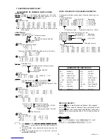
ASSIGNMENT OF COMMON PARTS CODES.

RESISTORS

R

1) GD05 x x x 140, Carbon film fixed resistor, 5% 1/4W

R

2) GD05 x x x 160, Carbon film fixed resistor, 5% 1/6W

1 Resistance value

Examples

1  Resistance value

0.1

..... 001

10

...... 100

1k

...... 102

100k

...... 104

0.5

..... 005

18

...... 180

2.7k

...... 272

680k

...... 684

1

..... 010

100

...... 101

10k

...... 103

1M

...... 105

6.8

..... 068

 390

...... 391

22k

...... 223

4.7M

...... 475

Note : Please distinguish 1/4W from 1/6W by the shape of parts

used actually.

CAPACITORS

C            : CERAMIC CAP.

3) DD1 x x x x 370, Ceramic capacitor

Disc type
Temp.coeff. P350~N1000, 50V

3  Capacity value

2  Tolerance

   Examples

2  Tolerance (Capacity deviation)

 0.25 pF ....... 0

 0.5 pF ....... 1

   5 % ....... 5

Tolerance of COMMON PARTS handled here are as follows :

0.5 pF - 5 pF .......  0.25 pF

  6 pF - 10 pF .....  0.5 pF

  12 pF - 560 pF ...  5 %

3   Capacity value

0.5 pF .... 005

3 pF ..... 030

100 pF ..... 101

1 pF .... 010

10 pF ..... 100

220 pF ..... 221

1.5 pF .... 015

47 pF ..... 470

560 pF ..... 561

C            : CERAMIC CAP.

4) DK16 x x x 300, High dielectric constant ceramic

capacitor
Disc type
Temp.chara. 2B4, 50V

4   Capacity value

   Examples

4   Capacity value

100 pF ..... 101

1000 pF .... 102

10000 pF .... 103

470 pF ..... 471

2200 pF .... 222

C

: 5) ELECTROLY CAP.(       ), 6)FILM CAP (       )

5) EA x x x x x x 10, Electrolytic capacitor

    One-way lead type,Tolerance  20%

6   Working voltage

5   Capacity value

   Examples

5   Capacity value

0.1

F .... 104

4.7

F .... 475

 100

F ..... 107

0.33

F .... 334

 10

F .... 106

330

F ..... 337

1

F .... 105

22

F .... 226

1100

F ..... 118

2200

F .... 228

6   Working voltage

6.3 V ...... 006

25 V ..... 025

10 V ...... 010

35 V ..... 035

 16 V ...... 016

50 V ..... 050

6) DF15 x x x 350

Plastic film capacitor

DF15 x x x 310

  One-way type, Mylar  5% 50V

DF16 x x x 310

Plastic film capacitor
  One-way type, Mylar  10% 50V

 7   Capacity value

   Examples

7   Capacity value

0.001 F (1000 pF) ...... 102

    0.1 F ...... 104

0.0018 F ........................ 182

0.56 F ...... 564

0.01 F ........................ 103

 1 F ...... 105

0.015 F ........................ 153

1) The above CODES(R

,R

,C

,C

and C

) are omitted on the schematic diagram in

some case.

2) On the occasion, be confirmed the common parts on the

parts list.

3) Refer to “Common Parts List” for the other common

parts(Rl05, DD4, DK4).

NOTE

NOTE ON SAFETY:

Symbol      Fire or electrical shock hazard. Only original
parts should be used to replaced any part marked with
symbol      Any other component substitution ( other than
original type), may increase risk of fire or electrical shock
hazard.

990521 A.O

NOTE ON SAFETY  FOR FUSIBLE RESISTOR :

The suppliers and their type numbers of fusible resistors are as
follows ;
1 . KOA Corporation
 Part No.(MJI)

Type No.(KOA)

 Description

NH05 x x x 140

RF25S x x x x 

J
J

J

J

5% (1/4W)

NH05 x x x 120

  RF50S x x x x 

5% (1/2W)

NH85 x x x 110

RF73B2A x x x x 

5% (1/10W)

NH95 x x x 140

RF73B2E x x x x 

5% (1/4W)

Resistance value       Resistance value(0.1  - 10k  )

2. Matsushita Electronic Components Co., Ltd
 Part No.(MJI)

Type No.(MEC)

 Description

NF05 x x x 140

   ERD-2FCJ x x x

( 5% 1/4W)

RF05 x x x 140
NF02 x x x 140

   ERD-2FCG x x x

( 2% 1/4W)

RF02 x x x 140

Resistance value

 Examples

Resistance value

0.1

..... 001

10

..... 100

1k

..... 102

100k

..... 104

0.5

..... 005

18

..... 180

2.7k

..... 272

680k

..... 684

1

..... 010

100

..... 101

10k

..... 103

1M

..... 105

6.8

..... 068

390

..... 391

22k

..... 223

4.7M

..... 475

ABBREVIATION AND  MARKS

ANT.

: ANTENNA

BATT.

: BATTERY

CAP.

: CAPACITOR

CER.

: CERAMIC

CONN.

: CONNECTING

DIG.

: DIGITAL

HP

: HEADPHONE

MIC.

: MICROPHONE

-PRO

: MICROPROCESSOR

REC.

: RECORDING

RES.

: RESISTOR

SPK

: SPEAKER

SW

: SWITCH

TRANSF.

: TRANSFORMER

TRIM.

: TRIMMING

TRS.

: TRANSISTOR

VAR.

: VARIABLE

X’ TAL

: CRYSTAL

:
:

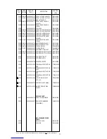
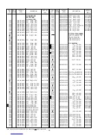
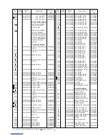
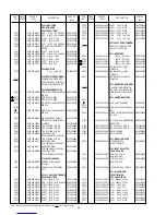
7. ELECTRICAL PARTS LIST


Summary of Contents for PM8200

Page 1: ...IRED FOR SERVICING 2 4 SCHEMATIC DIAGRAM AND PARTS LOCATION Pattern Side 3 5 EXPLODED VIEW AND PARTS LIST 15 6 IDLING CURRENT ALIGNMENT 18 7 ELECTRICAL PARTS LIST 19 PM8200 N1B N1G OFF ON OFF ON OFF O...

Page 2: ...Technical MARANTZ JAPAN INC MARANTZ JAPAN INC 35 1 7 CHOME SAGAMIONO SAGAMIHARA SHI KANAGAWA JAPAN 228 8505 PHONE 81 42 748 1013 FAX 81 42 741 9190 EUROPE TRADING EUROPE TRADING MARANTZ EUROPE B V MAR...

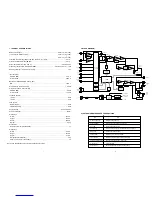
Page 3: ...AA size dry cell battery x 2 Design and specifications are subject to change without notice 3 TEST EQUIPMENT REQURED FOR SERVICING 2 BLOCK DIAGRAM PHONO SPEAKER OUT PROTECT INPUT REC SELECTOR RIAA CD...

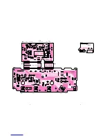
Page 4: ...2 WA319J101 2 TO J904 P101 RC5G PHONO CD OFF TUNER CDR MD TAPE MD TAPE CDR 0 0 0 0 0 4 0 4 0 0 0 0 0 0 0 0 0 0 0 0 0 0 0 0 0 0 0 4 0 0 0 4 7 6 5 3 2 1 8 7 6 5 4 3 2 1 W801 FROM J905 P101 TO W801 P101...

Page 5: ...114 U124 U125 U126 U127 U128 U129 U131 U132 C614 R622 R618 R624 R623 C613 R617 R619 R615 R621 C612 C611 C601 R601 R603 C603 C602 R602 R604 C604 R609 R610 R611 R612 R608 R607 R605 R606 R613 R614 R616 R...

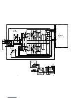
Page 6: ...220 50V 220 50V 100 25V 100 25V 0 01 0 01 100p 100p 100p 100p 0 01 100p 100p 0 01 100p 100p 0 01 0 01 100p 100p 100p 100p 0 01 100p 100p 330p 330p 22 25V 22 25V 47k 47k 100 25V 100 25V 22k 22k 22 0 02...

Page 7: ...U249 U250 U251 U252 U253 U254 U255 U256 U257 U258 U259 U260 U261 U262 U263 U264 U265 U266 U268 U269 U270 U271 U272 U273 U274 U281 U282 U283 U284 U285 U286 U287 U288 U289 U290 U291 U292 U293 U294 U295...

Page 8: ...A1048 Y GR 2SA1048 Y GR 2SA1048 Y GR 2SA1048 Y GR 2SC2458 Y GR 2SC2458 Y GR 2SC2458 Y GR 2SC2458 Y GR 2SA1048 Y GR 2SA1048 10 25V 10 25V 22 25V 22 25V 50 0 22 50 0 22 1 2k Y GR 2SA1048 10k 10k 470k 33...

Page 9: ...J502 J503 S501 R529 L501 U501 U502 U503 U504 U505 U506 U507 U508 U509 U510 U512 U514 U515 U516 U517 U518 U519 U520 U521 U522 C501 C502 C503 C504 C507 C508 C509 C510 C519 C520 J501 Q503 Q504 Q505 Q506...

Page 10: ...8 M x 2 0 0 5 B 5 1 2 8 3 X 8 M x 2 P 9 5 1 5 1 2 8 3 X 8 M 0 3 4 B 0 3 5 B P 2 9 1 P 8 9 1 0 1 9 B P 2 0 1 P 2 7 1 5 1 2 8 3 X 8 M x 4 0 0 9 B 0 4 2 B P 2 5 1 5 1 2 8 3 X 8 M x 5 5 1 5 0 3 X 8 M x 2...

Page 11: ...3 IR LENS BLACK 275W355010 031B GOLD 9965 000 01392 IR LENS GOLD 275W355110 034B 9965 000 01394 POWER BUTTON JOINT 312J125010 035B BLACK 9965 000 01975 POWER SW BUTTON BLACK 255W270010 035B GOLD 9965...

Page 12: ...tage input to the test points at the two extremities of three test points of R769 L ch and R770 R ch 2 After the setup above turn the mains switch ON and heat up the amplifier about 10 minuetes 3 Adju...

Page 13: ...ilm capacitor One way type Mylar 10 50V 7 Capacity value Examples 7 Capacity value 0 001 F 1000 pF 102 0 1 F 104 0 0018 F 182 0 56 F 564 0 01 F 103 1 F 105 0 015 F 153 1 The above CODES R R C C and C...

Page 14: ...7602520 C806 4822 124 22698 ELECT 47 F M 25V OA47602520 C807 9965 000 09801 ELECT 47 F 25V OA47602540 C808 9965 000 09801 ELECT 47 F 25V OA47602540 C809 4822 124 90366 ELECT 220 F M 50V OA22705020 C81...

Page 15: ...02A0 Q712 Q713 4822 130 43233 TRS 2SC2240 GR OR BL HT322402A0 Q714 4822 130 43233 TRS 2SC2240 GR OR BL HT322402A0 Q715 4822 130 42949 TRS 2SA970 GR OR BL HT109702A0 Q716 4822 130 42949 TRS 2SA970 GR O...

Page 16: ...10 F M 25V OA10602520 C602 4822 124 41534 ELECT 10 F M 25V OA10602520 C603 9965 000 01581 ELECT 22 F M 25V OA22602520 C604 9965 000 01581 ELECT 22 F M 25V OA22602520 C611 4822 124 41534 ELECT 10 F M...

Page 17: ...822 130 60107 TRS 2SA1048 Y OR GR HT110482B0 Q505 4822 130 60839 TRS 2SC2458 Y OR GR HT324582B0 Q508 Q509 4822 130 60107 TRS 2SA1048 Y OR GR HT110482B0 Q512 Q513 4822 130 60839 TRS 2SC2458 Y OR GR HT3...

Reviews: