


B
B
A
C
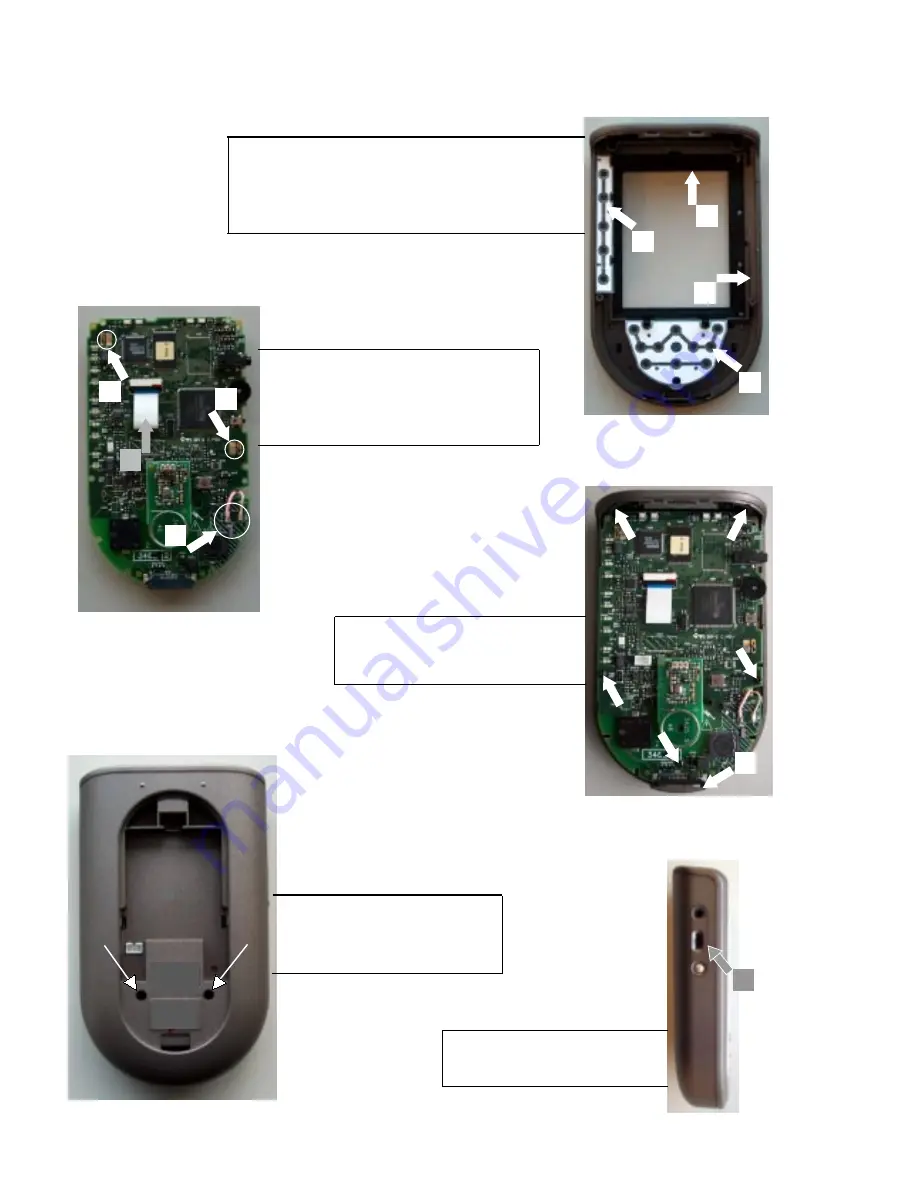
MECHANICAL INSTRUCTIONS - TS9201
1. Put Toppart (*item1) and IR-wind assy (*item 4) together.
2. Place Toppart assy (item1 & item4) upside down.
3. Place upper keymat assy. (*item8)
4. Place LCD keymat assy. (*item9)
Set Reassembly
1a. Put printboard on LCD assy. (*item15)
2a. Soldering the 2 fixation points. see arrow B
3a. Connect the flex cable. see arrow A
4a. Solder the two wires. see arrow C
8. Place bottonpart assy (*item2)
9. Mount the two screws. see arrow
10. Place battery pack. (*item34)
11. Place batterylid assy. (*item3)
1-3
5. Place mainboard in the toppart.assy.
6. Place Doc. plug assy. (*item7)
7. Mount the 5 screws back. see arrows
Reassembly LCD & Mainboard
12. Place plug insert assy. (*item6)
see picture - arrow
4
1
8
9
6
* for items see overview disassembled parts
7
Summary of Contents for RX-77
Page 19: ...DOCKING STATION DS9200 5 1 ...
Page 23: ...3104 207 11520 bl132 dd 14 03 02 7 1 CHARGE BOARD Component Layout ...
Page 26: ...IR RF RECEIVER RX 77 9 1 ...
Page 30: ...RF RX1 BOARD Component Layout 11 1 3104 207 1131 bl132 1 dd 12 02 02 ...
Page 31: ...3104 207 1216 bl132 1 dd 11 07 02 PF BLASTER BOARD Component Layout 11 2 ...


