3.8 “ BACKUP” Indicator (GREEN LED)
This LED illuminates when the UPS is supplying battery power to the loads.
3.9 “ BOOST (AVR)” Indicator (YELLOW LED)
This LED illuminates when the UPS is correcting a voltage sag or undervoltage condition. The load
receives normal power.
3.10 “ REPLACE BATTERY” Indicator (RED LED)
This LED illuminates when the UPS's battery is no longer useful and must be replaced. See section 10.
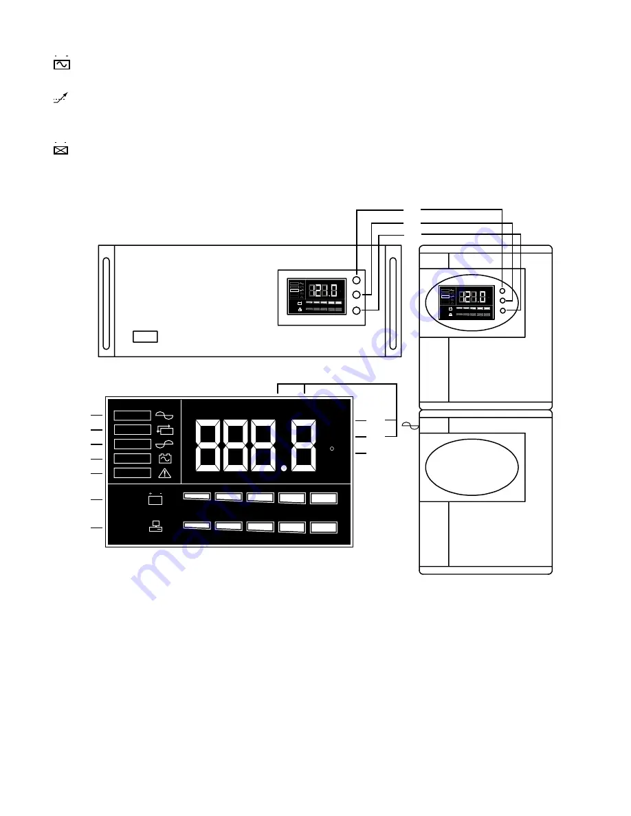
For units with an LCD display
3.11 “ ON/TEST” Button
Once connected, pressing this button turns the UPS on and powers the loads. It also activates the
UPS's self-test and utility line voltage displays.
3.12 “ OFF” Button
Pressing this button turns OFF the UPS and its connected loads.
3.13 “ SELECT” Button
Depressing and holding the select button cycles through various LCD display modes. Modes include:
Input Voltage, Output Voltage, Input Frequency, Output Frequency, Internal Temperature and Load (%).
ON
OFF
SELECT
Vac
BATT
LOAD
Hz
I/P
O/P
INV
LINE
BY PASS
INV
BACKUP
FAULT
C
0 %
20 %
40 %
60 %
80 %
100 %
0 %
20 %
40 %
60 %
80 %
100 %
Vac
BATT
LOAD
Hz
I/P
O/P
INV
LINE
BY PASS
INV
BACKUP
FAULT
C
0 %
20 %
40 %
60 %
80 %
100 %
0 %
20 %
40 %
60 %
80 %
100 %
ON
OFF
SELECT
Vac
BATT
LOAD
Hz
I/P
O/P
INV
LINE
BY PASS
INV
BACKUP
FAULT
C
0 %
20 %
40 %
60 %
80 %
100 %
0 %
20 %
40 %
60 %
80 %
100 %
3.11
3.12
3.13
3.14
3.15
3.16
3.17
3.18
3.19
3.20
3.21
3.22
3.23
LCD RACK MOUNT MODELS
LCD TOWER MODELS
LCD DISPLAY DETAIL
(not to scale)
3


