background image

APPENDICES


TRTC-2002-N1 Specifications


PTS Specifications

Battery Care

HyperTerminal Set-Up

TRTC-2002-N1 Specifications

Functions 

Brownout Protection

This unit boosts the output voltage (or 

transfers to battery) during brownout or low 

input line conditions and returns to On Line 

when input power stabilizes and returns to 

normal. The values for Transfer / 

Retransfer, To / From Battery / Boost mode 

are user programmable. 

Generator Compatibility 

Generator mode allows for more variations 

in input voltage and frequency for use with 

an AC generator. 

Battery Charger 10A 

PFC switch-mode charger is temperature-

compensated (-3 to -5 mV/°C /Cell) with 

automatic shut off above 50°C. 

Inverter Mode 

Capable of running continuously in inverter 

mode. 

Inverter Mode Current 

Limit 

Continuous electronic current limit is 

provided. 

Measurements   

available for remote  

monitoring 

- Input and output voltages 

- Input line frequency 

- Battery voltage and current 

- Battery and heat sink temp 

Mechanical Specifications


Dimensions (H x W x 
D), inch (mm) 

5.25” x 17” x 10.5”, 3U size 

(133 mm x 432 mm x 267 mm) 

Weight, lb (kg) 

46.2 (21) 

Input Connection 

Anderson PP45/4P Connect 

Output Connection 

Anderson PP45/4P Connect 

Mounting 

19” (483 mm) or 23” (584 mm) rack or 

shelf mount 

Cooling 

Microprocessor controlled, 12VDC, 

3.62” (92 mm) fan 

Audible Noise Level, 

 dBA 

<40 

Operating 

Temperature, 


-37° to +74°C 

(See Notes 1 and 2) 

Storage Temperature 


-50° to +75°C 

Humidity 

Less than or equal to 95%, Non-Condensing 

Altitude, ft (m) 

10,000 (3048) (See Note 2) 

HyperTerminal at a Glance

PuTTY at a Glance

Step by Step Connecting to Windows XP

Step by Step Connecting to Windows 7

Electrical Specifications 

Output Apparent Power, VA 

2000 (Inverter Mode) 

2000 (Line Mode)

Output Active Power, W

1500 (Inverter Mode) 

1500 (Line Mode)

Power Factor 

0.75 

Input Frequency, Hz +/- 3HZ   

60 

Input Voltage Range, VAC 

90 to 150 VAC User program-   

able. Defaults set @ 100~ 130 

VAC +/- 2 VAC. 

Output Voltage 

Inverter Voltage

120 Nom (Tolerances are user  

programmable) 

120 VAC+/-5%

Maximum Input Current, A 

30

Transformer

Linear (Non-Isolated)

Transfer Time, msec

<65 msec. Buck & Boost enable 

<10 msec. 

Inrush Current

Load dependent 

Output Waveform THD, %

< 3 (Resistive Load)

Load Crest Ratio 

3:1 

Efficiency, Line Mode

> 95% (Resistive Load) 

Efficiency, Inverter Mode 

> 80% (Resistive Load) 

Nominal Battery String   48VDC 

Voltage, VDC 

48VDC 

Step Load Response (50%) 

1 Cycle full recovery 

Over current Protection 

Double Pole Single Throw Circuit   

Breaker Rated at 30 Amp for input 

and output 

DC Bus: 60 Amp circuit breaker 

Transient Suppression 

MOV transient suppression 

elements (>150V) 

DC Power 

Drawn from batteries 

70

Summary of Contents for TRTC-2002-N1

Page 1: ......

Page 2: ...2...

Page 3: ...3 A TOUR OF YOUR TRTC 2002 N1 13 3 1 Front and Back Panel 13 3 2 Power Transfer Switch 18 SECTION 4 INSTALLATION 19 Warnings Tips 19 4 1 Mounting 19 4 2 Recommended Wiring 20 4 3 Connecting the Outpu...

Page 4: ...4 Main Menu 51 6 5 Submenus 53 6 6 Unit Specifications 53 6 7 Input Output Values 53 6 8 Maintenance 53 6 9 Line Slow Detection Parameters 56 6 10 Parameter Change Procedure 56 6 11 Parameter Descrip...

Page 5: ...aintenance 68 9 7 Battery Maintenance 68 APENDICES 70 TRTC 2002 N1 Specifications 70 PTS Specifications 72 Battery Care 73 HyperTerminal Set Up 74 HyperTerminal at a Glance 76 PuTTY at a Glance 77 Ste...

Page 6: ...icates that the instructions should only be carried out by qualified personnel Safety Symbols Before Getting Started System Safety Checklist Battery Safety Checklist Stand By Generator Servicing Safet...

Page 7: ...acturer cabinet ensure that the environment meets the system specifications shown in the Appendix Do not expose the TRTC 2002 N1 to rain or moisture Total Earth ground leakage current of loads connect...

Page 8: ...s Recycling is the best method Never burn batteries to dispose of them They may explode Do not open the batteries The contents are toxic Stand By Generator If the TRTC 2002 N1 constantly switches betw...

Page 9: ...he following for records future servicing Model No TRTC 2002 N1________________ _ Serial No ___________________________________ Above items can be found on the nameplate label attached to the side of...

Page 10: ...irect Current Institute of Electrical and Electronics Engineers Electronic Industries Association Institute of Transportation Engineers Kilovolt Ampere Light Emitting Diode Liquid Chrystal Display Nat...

Page 11: ...ated internal charger continuously monitors and maintains the batteries in a fully charged state For the protection of the battery the charging process is automatically discontinued when the battery t...

Page 12: ...02 N1 2 2 System Description Purpose Describes the operation of the TRTC 2002 N1 System The TRTC 2002 N1 System provides backup power to traffic control signal equipment It consists of the PB2000 Unin...

Page 13: ...ttery Connector Connects the battery to the unit The battery string voltage is 48VDC 2 Battery Circuit Breaker Acts as an ON OFF switch for battery power Must be in the ON position for normal operatio...

Page 14: ...tenance or replacement Must be in the ON position for normal operation 6 AC Input Inlet Anderson PP45 4P provided for the input of line power 7 AC Output Outlet Anderson PP45 4P provides the connectio...

Page 15: ...al block provides communication with the intersection controller controls the Power Transfer Switch PTS and Programmable Input contact Figure below shows its layout and operation Green Terminal Block...

Page 16: ...ry default value is 2 hours The time can be programmed to be from 15 min to 8 hours in 15 minute increments Program Input The programmable input contact can be programmed for one function such as Self...

Page 17: ...is not charging the batteries check the temperature probe To test the temperature probe unplug it from the face of the UPS Check the resistance of the temperature probe by inserting the probes of an...

Page 18: ...power is connected to the terminal block marked with AC OUTPUT 4 An optional surge suppressor external PC optional battery heater or a vacuum cleaner for maintenance may be plugged into these recepta...

Page 19: ...e wired into the traffic signal cabinet The intent of this manual is only to explain proper connection of utility AC at the UPS end of the cable How the Utility AC is routed from the service entrance...

Page 20: ...Style 1015 CSA TEW 10 AWG b 105 stands of 30 AWG tinned copper c Rating 600V 105 C PVC Insulation 3 Relay connections a Insulated UL Style CSA TEW 18 AWG b 16 stands of 30 AWG tinned copper c Rating 6...

Page 21: ...round the strain relief loop and the battery temperature sensor to prevent the connector from disconnecting during an earthquake or other severe vibrations Attach External Cabinet Fan into the respect...

Page 22: ...Connect the BYPASS CONTROL wires to the PTS connector into the TRTC 2002 N1 Connect the PTS UPS IN to the UPS AC INPUT Attach PTS UPS OUT to the UPS AC OUTPUT 22...

Page 23: ...s are activated as soon as the unit is transferred to Battery mode LOW BATTERY contact s are activated only in the Battery mode as soon as the discharged battery reaches the lower value battery capac...

Page 24: ...at the UPS end of the cable How the Utility AC is routed from the service entrance or through the traffic signal cabinet hereafter referred to as the power source to the UPS shall be determined by a l...

Page 25: ...IT BREAKER on the unit is also off Make sure the upstream circuit breaker feeding the utility power is OFF before beginning this step Leave the NEUTRAL and GROUND wires connected from utility to signa...

Page 26: ...he AC breaker is not ON the UPS will stay in STANDBY and can only be placed ON BATTERY manually to prevent accidentally leaving the intersection in operation on batter power without restoring AC power...

Page 27: ...iately restore the AC power for the intersection at the upstream circuit breaker Turn OFF the upstream circuit breaker The OUTPUT Green LED will flash and the LCD displays ON BATT indicating that outp...

Page 28: ...AC input Output wires and insulate Disconnect mark and insulate wires at the Green Control Terminal Block the plug for Ext Fan the plug for battery temperature sensor and the RS232 or USB connector R...

Page 29: ...as well as an optional generator power if utilized Disconnecting all the AC and DC power sources will ensure that the output circuit is not live Turn OFF the battery circuit breaker Turn OFF the AC in...

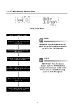
Page 30: ...he wires from AC IN NEUTRAL GROUND and AC OUT from the PTS Remove and perform the maintenance on the PTS Perform this procedure in the reverse order to reinstall the PTS NOTE IMPORTANT Verify that bot...

Page 31: ...intenance Change Password Maintenance Current UPS Status Status Daylight Saving Settings Enable Boost Settings Enable Buck Settings Event Log View Maintenance Events Timer Reset Control Ext Fan Contro...

Page 32: ...and 5 10 Alarm Menu appears on the LCD screen The status submenu provides measurements of important TRTC 2002 N1 inputs output and other parameters via the LCD screen see Section 5 6 Status The contro...

Page 33: ...arms See Table 4 20 Faults See Table 3 01 Self Test 02 Program Contacts Test 03 Ext Fan Test 04 Manual On Reset 05 Events Timer Reset 06 Log Reset 07 Password Protection 01 Program Contacts See Table...

Page 34: ...nt is complete LCD Panel Key Function When the ambient air temperature drops below 20 C 4 F the LCD may turn DARK until the temperature rises above 20 C 4 F However the unit will operate normally Turn...

Page 35: ...user programmable preset limit ON BATT The unit automatically transfers to battery when input line power is unqualified or not present The batteries provide power to the loads BUCK The unit automatica...

Page 36: ...The average battery voltage Battery Temperature S T A T U S Batt Temp 24 C The temperature of Battery case Inv Events S T A T U S Inv Events 00016 The number of times the unit has been in Battery Mode...

Page 37: ...ion 2 2 2 2 The software version used in this unit 2 2 Control board 2 2 LCD Board Program Input Contact S T A T U S Program I P Contact It indicates Programmed values of Input Contact Program Contact...

Page 38: ...ESET C O N T R O L Manual On Reset This function is available only when the unit is first turned on the LCD shows Standby Pressing ENTER manually starts the unit and the Battery supplies the output po...

Page 39: ...RNAL FAN CONTROL S E T T I N G S Ext Fan Control Indicates temperature setting for external fan SENSE TYPE S E T T I N G S Sense Type Toggle between Generator Generator parameter and Normal Normal par...

Page 40: ...selected here in 1 minute increments The TRTC 2002 N1 can be tested to run on Battery for Maintenance purposes here INVERTER ON OFF MAINTENANCE Inverter On Off Inverter can be turned ON or OFF This o...

Page 41: ...plugged The battery temperature probe is unplugged or damaged When the unit detects the probe is unplugged it will continue to operate but the charger voltage will automatically be set to the lowest v...

Page 42: ...uited or the inverter did not start Batt Low Volt Low Battery Voltage The batteries output voltage is low Batt High Volt High Battery Voltage The batteries output voltage is high Temp High High Temper...

Page 43: ...each one of the 16 digits indicates a unique event A value of 1 indicates the presence of an event represented by the position of that digit while a value of 0 indicates an absence of that event The a...

Page 44: ...onditioning High Hyst 145 V AC Line Conditioning High Limit 150 V AC Line Conditioning Input Output Values Input Output Values Inverter On Off available in Standby Battery Mode Maintenance Line Qualif...

Page 45: ...6 2 Menu Tree 45...

Page 46: ...46...

Page 47: ...47...

Page 48: ...48...

Page 49: ...s on the laptop computer that will be used to interface Take notice of the installation order First run the InstallShield wizard and then plug in the USB cable from the unit to the laptop The followin...

Page 50: ...e it either The commercial products HyperTerminal Private Edition and HyperACCESS support all versions of Windows up to and including Windows 7 http en wikipedia org wiki HyperTerminal HyperTerminal i...

Page 51: ...N1 0 MAIN MENU 1 Unit Specification 2 Input Output Values 3 Maintenance 4 Line Conditioning Setup 5 Programmable Contacts Setup 6 Event Log View 7 Load Setup Defaults Date Time 07 06 11 16 16 57 Sense...

Page 52: ...eading EEPROM Wout Hi Output Power High Overload Bad Battery Bad Battery ALARM DISPLAYS Vout Lo Output Voltage Low Lout Hi Output Current High Overload Output Overload Temp Hi Ambient Battery Temperat...

Page 53: ...ominal output voltage Output VA 2000 VA The output VA capacity Battery Voltage 48 Volts Nominal battery capacity Max Charge Current 10 amps MAX charge capacity EEPROM Version 02 2 EEPROM version of th...

Page 54: ...02 N1 switches to STANDBY mode when this option is activated 32 Inverter On Off During the BATTERY or STANDBY mode this option allows the inverter to be switched OFF or turned ON after the user progra...

Page 55: ...C above which the 48VDC power will be provided for external cooling fan The temperature can be set in 1 C increment from 20 to 55 C The factory default temperature is set at 25 C Password Changing Pr...

Page 56: ...winding When activated the transformer will automatically switch to the secondary tap to buck or boost the voltage output 10 thereby keeping the output within an acceptable range Improperly set param...

Page 57: ...level TRTC 2002 N1 releases the Buck Mode when enabled and transfers back to the Line Mode Buck to Line DISABLE 125VAC Buck High High Gap Normal 44 Slow Detect Boost High When input voltage returns ab...

Page 58: ...Status Home Summary Information Data Log Log Data Log Data Log Length Log Log Settings Date and Time Setting System Date and Time Display Event Logs Log UPS Event Log DNS Configuration System Network...

Page 59: ...Using one of the methods above connect the Ethernet port on your computer to the Ethernet center port on the NetPower card Then open a web browser and enter 192 168 1 51 into the address bar If you a...

Page 60: ...booted To reboot the network interface card either 1 Completely power down the TRTC 20002 N1 or 2 Remove the two screws securing the network interface card to the TRTC 2002 N1 and then remove the card...

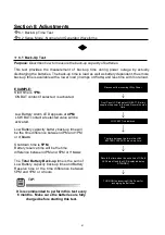
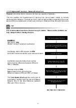
Page 61: ...time LOW BATT is displayed The time between the two is the LOW BATTERY CAPACITY back up time Record the time when the unit shuts off Both LEDs are off and the LCD display indicates STANDBY TURN ON th...

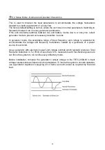
Page 62: ...or mode the acceptable range of input frequency and voltage is expanded to accommodate the voltage and frequency fluctuations created by a generator or a power source of such kind Use a generator with...

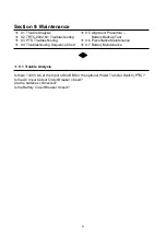
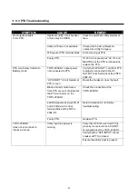
Page 63: ...TS Troubleshooting 9 6 Preventative Maintenance 9 4 Troubleshooting Sequence Chart 9 7 Battery Maintenance 9 1 Trouble Analysis Is there 120V AC at the Input of the BBS or the optional Power Transfer...

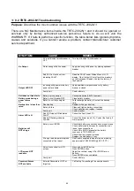
Page 64: ...than rated Battery not connected Connect batteries 48VDC nominal Battery circuit breaker OFF Close battery breaker Battery is not fully charged Fully recharge the battery then test the backup time Dea...

Page 65: ...he AC OUTPUT terminal block at the TRTC 2002 N1 UPS INPUT circuit breaker at PTS is open Reset the breaker clear the fault Black and red control wires from PTS are not connected at the PTS connector o...

Page 66: ...isonnect the wires from AC IN NEUTRAL GROUND and AC OUT from the PTS Remove and perform the maintenance on the PTS Perform this procedure in the reverse order to reinstall the PTS NOTE IMPORTANT Verif...

Page 67: ...ord the start time LOW BATT is displayed The time between the two is the LOW BATTERY CAPACITY back up time Record the time when the unit shuts off Both LEDs are off and the LCD display indicates STAND...

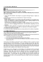
Page 68: ...of batteries There are several factors that all contribute to the useful life of the batteries used with the UPS 1 The ambient temperature around the UPS 2 How many times the batteries are discharged...

Page 69: ...t as is in its original packing and shipping container 2 The optimum storage temperature range is 5 F to 77 5 C to 25 3 Ensure that the equipment is fully protected from wet or damp areas and from moi...

Page 70: ...19 483 mm or 23 584 mm rack or shelf mount Cooling Microprocessor controlled 12VDC 3 62 92 mm fan Audible Noise Level dBA 40 Operating Temperature 37 to 74 C See Notes 1 and 2 Storage Temperature 50 t...

Page 71: ...ry connected f High temperature g Low temperature 5 Fault any of the following conditions occur a Short circuit b Batt low voltage c Batt high voltage d High temperature e Overload B Provides 48 VDC s...

Page 72: ...Storage Temp 50 to 75 C Humidity Non Condensing 95 Attitude Note 2 10 000ft 3000 m PTS MECHANICAL Dimensions WxDxH inch mm 4 75 120 6 W 6 5 165 D 4 6 116 8 H Weight lb kg 7 0 3 2 Mounting Rack Mount...

Page 73: ...d batteries the life of a battery can be reduced to two to three years If batteries are overly discharged or left standing in the discharged state for prolonged periods hardened lead sulfate coats the...

Page 74: ...such as COM1 COM2 etc Hyper Terminal Selection Screen Step 1 The path is Programs Accessories Communications HyperTerminal as shown Step 2 Click on the HyperTerminal icon The Connection Description sc...

Page 75: ...gs Tab Select the fields as shown Step 7 Click the ASCII Setup button Step 8 Select the fields in the ASCII Setup screen as shown Step 9 Click OK The properties window re appears Step 10 Click OK Hype...

Page 76: ...HyperTerminal at a Glance 76...

Page 77: ...PuTTY at a Glance Remember to return to the Session Panel and hit save to save your settings 77...

Page 78: ...networking port An AutoLink port will determine if you are connecting to a device that requires a crossover cable or a straight through cable and automatically transmit and receive using the correct...

Page 79: ...Local Area Connection or Right click on the Local Area Connection that you are using to connect to the NetPower Card click Properties STEP 3 If you double clicked you will be presented with this scre...

Page 80: ...ng the properties dialog box highlight Internet Protocol Version 4 STEP 5 You will be presented with the dialog box below enter the IP Address 192 168 1 253 with a subnet mask of 255 255 255 0 click O...

Page 81: ...168 1 51 into the address bar If you are prompted for a username and password enter Enter Username admin Password user STEP 8 Click on the Regular Interface link then go to the System Tab Network and...

Page 82: ...termine if you are connecting to a device that requires a crossover cable or a straight through cable and automatically transmit and receive using the correct connection Record the settings that are a...

Page 83: ...Local Area Connection or Right click on the Local Area Connection that you are using to connect to the NetPower Card click Properties STEP 3 If you double clicked you will be presented with this scre...

Page 84: ...ng the properties dialog box highlight Internet Protocol Version 4 STEP 5 You will be presented with the dialog box below enter the IP Address 192 168 1 253 with a subnet mask of 255 255 255 0 click O...

Page 85: ...1 51 into the address bar If you are prompted for a username and password enter Enter Username admin Password user STEP 8 Using the Regular Interface and go to the System Tab Network and enter the ap...

Page 86: ...e following Telephone Address Clearly write the RMA number on the original shipping container If you do not have the original container pack the unit with at least three inches of shock absorbing mate...

Page 87: ......

Page 88: ......

Page 89: ......

Page 90: ......

Page 91: ......

Page 92: ...2017 Marathon Power Inc TRTC 2002 N1 User Manual_Jan_2017 2017 Marathon Power Inc...

Reviews: