

INSTRUCTIONS FOR THE ELECTRICAL INSTALLATION OF THE WHISTLE
AND SETTING OF THE SIGNAL TONES
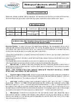
Waterproof electronic whistle
12V/24V
Codice
136 001 12 (12V)
136 001 13 (24V)
Electronic whistle complete with loudspeaker, microphone and electronic controller with functions
of: 800Hz frequency generator, automatic fog signal, class A/B voice amplifier, AUX Input.
TECHNICAL DATA
Important Notice.
In order to ensure complete water-tightness, the loudspeaker driver unit is
supplied with a factory fitted electrical cable 0.5 m long, tin-plated and 2 x 0,75 mm² section. Do
not replace this cable or open the driver unit, warranty will be invalidated. A suitable terminal
junction box should be used to complete the cable connections.
1.Mount the loudspeaker in a slightly downward tilt position in order to prevent water entrapment
inside the cone.
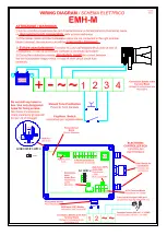
2.Open the Electronic Controller coverlid and identify the marked 8 pins terminal block and 4 pins
terminal block.
3.Complete the electrical installation as shown in the attached wiring diagram.
4.Device wiring for functions activation (refer to the attached installation diagram)
a.
Manual Tone.
To obtain a manually activated free tone, install a pushbutton switch control
across the terminal contacts marked 1 and 2 on the 8 pins terminal block. The maximum duration
of a continuous blast is 5”.
NOTE - THIS PUSHBUTTON HAS ALWAYS ABSOLUTE PRIORITY OVER ALL OTHER
FUNCTIONS, INCLUDING THE MICROPHONE.
b.
Fog Horn Signal-90 seconds.
A fog-horn signal repeated at specified intervals is obtained
connecting the switch in position closed (connections across the terminal pins marked 1 and 3 on
the 8 pins terminal block). The signal is a tone of 5” duration.
c.
AUX Input.
Amplifier auxiliary input ( suitable for signals : VHF, radio, CD, mp3…). Voltage
input range : 200mV…3V RMS. Wiring instructions for the 4 PIN screw connector in the draw
attached : signal on “~” and “~”, function activation switch between “ 1 ” and “ 2 “. Adjust the level of
the output sound with the trimmer located beside the 4 pin connector. If the sound level is not
enough loud even with the trimmer at the extreme position or the background noise is high, please
reverse the connection of the two signal wires marked with “~” on the 4 pins terminal block.
d.
Microphone.
Connect the microphone to the microphone socket, then adjust the output
level with the trimmer located in the middle of the printed circuit board. Depending on relative
position and distance of microphone and loudspeaker the Larsen effect may occur, in this case
reduce the gain with the trimmer.
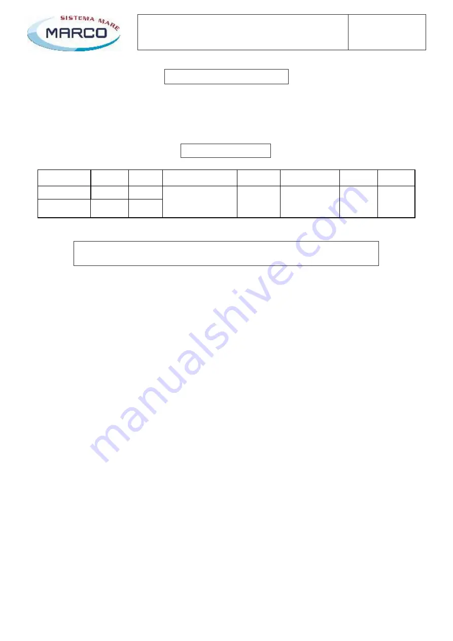
PRODUCT DESCRIPTION
Product Code
V
A
Acoustic Power
Fog signal
frequency
Horn Dimensions
Total Kit
Weight
protection
13600112
12
1,5
13600113
24
1
Pilot electrical power
12 W
Acoustic Pressure at
1 m 108 dB
800Hz
154x121x132
1,550 kg
IP 67


