background image


1000870,871,875,878,879,880,887 MIX Service Manual.b 


Page 38 of 69


8.14 Changing the Filter


Summary of Contents for MIX PB3

Page 1: ...9 880 887 MIX Service Manual b Page 1 of 69 MIX Boiler Font Range Service Manual 1000870 1000871 1000875 1000880 1000887 1000878 1000879 2300268 www marcobeveragesystems com Ireland Tel 353 1 295 2674 UK Tel 44 0207 2744577 ...

Page 2: ...ineering Settings 24 7 4 Dispense Calibration 25 8 Routine Maintenance Internal Access 26 8 1 Top Lid Removal 26 8 2 Side Panel Removal 26 8 3 Draining the Tank 27 8 4 PCB Replacement 28 8 5 Dispense Solenoid or Pump replacement 29 8 6 Dispense Tap removal 30 8 7 Tank Lid Sub Assembly Removal 31 8 8 Heater Element Removal 33 8 9 Thermistor Level Probes Cleaning replacement 33 8 10 Triac Replacemen...

Page 3: ...y tested to 190psi However a hose is not a permanent connection It is therefore advisable to switch off boiler and close the stopcock valve when boiler is not in use e g overnight etc The utmost care has been taken in the manufacture and testing of this machine Failure to install maintain and or operate this machine according to the manufacturer s instructions may result in conditions that can cau...

Page 4: ... Earthed Mains Plug to IEC 230vac UK 3 Pin Plug BS1363 EU CEE7 Schuko US Canada NEMA L6 20P Rating 230V 2 8kW 12 15A Plumbing Fittings Required Pressure 0 75 BSP or 3 8 NPT for US versions food grade inlet hose supplied 5 50 psi 35 345 kPa Dimensions Height mm Width mm Depth mm 420 210 440 590 210 505 590 210 440 440 210 385 610 210 385 FONTS MIX Single Button Font 1000870 MIX Three Button Font 10...

Page 5: ...n Mains water pressure required limits 5 50psi 35 345kPa 0 5 5 0 bar Fit a stop Valve on a cold water line and attach a 3 4 BSP male fitting e g 3 4 x 1 2 311 or washing machine type stop valve For US versions use 3 8 NPT male fitting Connect straight tailpiece of the hose to the stop valve fitting Make sure that the pre attached sealing washer is fitted Turn on the water to flush any impurities d...

Page 6: ...1000870 871 875 878 879 880 887 MIX Service Manual b Page 6 of 69 4 1 Mix Boiler Installation cont ...

Page 7: ...1000870 871 875 878 879 880 887 MIX Service Manual b Page 7 of 69 4 2 Mix Font Installation ...

Page 8: ...1000870 871 875 878 879 880 887 MIX Service Manual b Page 8 of 69 4 2 Mix Font Installation cont ...

Page 9: ...1000870 871 875 878 879 880 887 MIX Service Manual b Page 9 of 69 4 2 Mix Font Installation cont ...

Page 10: ...1000870 871 875 878 879 880 887 MIX Service Manual b Page 10 of 69 4 2 Mix Font Installation cont ...

Page 11: ...lti Temp versions Single Temp versions Tap Versions The Ready tick with come up on screen when the machine is full and up to normal operating temperature typically 6 mins for 3L and 16 mins for 8L versions respectively The boiler is now ready for use the display will show the Water Temperature and the Ready status tick Multi Temp versions Single Temp versions Tap Versions The Boiler may now be use...

Page 12: ...1000870 871 875 878 879 880 887 MIX Service Manual b Page 12 of 69 6 OVERVIEW OPERATION 6 1 PB Boiler Multi temp Operation ...

Page 13: ...1000870 871 875 878 879 880 887 MIX Service Manual b Page 13 of 69 6 1 PB Boiler Multi temp Operation cont ...

Page 14: ...1000870 871 875 878 879 880 887 MIX Service Manual b Page 14 of 69 6 2 PB Boiler Single Temp Operation ...

Page 15: ...1000870 871 875 878 879 880 887 MIX Service Manual b Page 15 of 69 6 2 PB Boiler Single Temp Operation cont ...

Page 16: ...1000870 871 875 878 879 880 887 MIX Service Manual b Page 16 of 69 6 2 Tap Boiler Operation ...

Page 17: ...1000870 871 875 878 879 880 887 MIX Service Manual b Page 17 of 69 6 2 Tap Boiler Operation cont ...

Page 18: ...1000870 871 875 878 879 880 887 MIX Service Manual b Page 18 of 69 6 3 UC Boiler Operation ...

Page 19: ...1000870 871 875 878 879 880 887 MIX Service Manual b Page 19 of 69 6 3 UC Boiler Operation cont ...

Page 20: ...1000870 871 875 878 879 880 887 MIX Service Manual b Page 20 of 69 6 4 Mix Font Operation ...

Page 21: ...Boiler or the Mix dispense font in the case of a UC version The second row shows the desired dispense volume a volume of 000 sets the dispense button to Push Hold mode Press NEXT to cycle through each value shown on the screen Press or to adjust a value Press SAVE to store values and return to normal operation Single temp PB and UC versions NOTE in single temp mode ONLY the middle dispense button ...

Page 22: ...to the Advanced and Engineering Level settings Blank any 4 digit combination Back door PIN in the event of forgotten PIN is 1793 Factory Preset Resets a number of Engineering Level settings specific to a machine type Allows selection of machine type from TAP PB3 PB8 UC 3 button UC 1 button Mode Allows selection of mode types from Mode Type T be used for UC COLD HOT UC version connected to 3 button...

Page 23: ...1000870 871 875 878 879 880 887 MIX Service Manual b Page 23 of 69 7 2 Advanced Settings cont ...

Page 24: ...r PB or UC versions Cal weight User measured amount of water dispensed during calibration process Default values depend on machine type PB3 600 PB8 1050 UC 3 button 600 UC 1 button 600 Inlet Flow The software calculated amount of water through the inlet solenoid into the boiler tank during the calibration process NOTE should not be edited once calibration process completed Default value 1200 Tank ...

Page 25: ...re done 1 Default settings for a PB3 Press Go 2 Place bucket Press Go 3 Machine will dispense for 15 seconds 4 Weigh output 5 Screen will show the above 6 Enter Weight using Press Next 7 Machine will refill to the high level 8 Screen will show entered CAL WEIGHT and software Time to refill is displayed on screen calculated INLET FLOW Press Next 9 The second Engineering settings screen 10 If the CO...

Page 26: ...out by Marco approved technicians only 8 1 Top Lid Removal 1 Remove the screw in the top lid with a suitable slotted screwdriver 2 Rotate lid from the front edge upwards and remove 8 2 Side Panel Removal For maintenance requiring deeper internal access both side panels can be removed by using a suitable cross headed phillips screwdriver ...

Page 27: ... or a bucket large enough to hold the full contents of the tank 4 Unclip drain hose plug from rear panel by rotating anti clockwise 90o 5 Gently pull silicone hose from the inside of the machine 6 Remove drain plug from the end of the silicone hose and empty into sink or bucket 7 Replace drain plug fully into silicone hose and push silicone hose gently back into the machine 8 Re clip the drain plu...

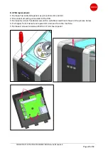
Page 28: ... Lid Side panels as per sections 8 1 and 8 2 2 Disconnect all wiring connected to the PCB 3 Remove two cross headed screws with a suitable screwdriver shown in the picture below 4 Pull Upper front Fascia Panel upwards to remove from the machine 5 Remove 4 screws to release PCB from Front Fascia panel ...

Page 29: ...ine For PB versions push the silicone dispense nozzle through the hole the nozzle will need to be squeezed slightly To remove the dispense solenoid in a PB version CAUTION make sure tank is drained fully first as per section 8 3 1 Disconnect all wires connected to solenoid 2 Disconnect cold water feed in to the Silicone dispense nozzle by pulling upwards 2 Pull dispense solenoid out of the silicon...

Page 30: ...p 2 Pull the silicone hose off the outlet side of the pump 3 Pull the pump out of the silicone mounting grommet 8 6 Dispense Tap removal To remove the dispense tap in any Tap version boiler CAUTION make sure tank is drained fully first as per section 8 3 1 Loosen Tap retaining nut by turning clockwise 2 When tightening the nut the spigot should be gripped and held in place by a 19mm spanner at the...

Page 31: ...8 1 and right hand side panel as per section 8 2 3 Disconnect heating element wires as well as disconnecting the level probe connector and thermistor connectors at the PCB 4 Undo the 3 Tank Lid retention screws located in the picture below For the screw underneath the collapsible funnel simply push funnel gently out of the way to access the screw 5 Gently pull the Tank Lid sub assembly upwards ini...

Page 32: ... is just over half way out of the tank start to angle the sub assembly towards the rear of the machine and begin to pull the forward bent section of the heating element out of the tank opening 7 Finish removal by then sliding the sub assembly forwards and upwards to disengage from Tank opening ...

Page 33: ...the Mix Boiler range Each probe is push fit mounted into a silicone mounting grommet The low level and thermistor are paired together in one grommet and the high level and overflow level probes are paired together in the other The Tank lid sub assembly does not need to be removed to access the level probes as they can be pulled from the silicone mounting grommet by the metal electrical tab the des...

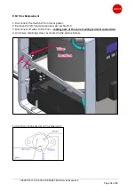
Page 34: ... 1 Disconnect the machine from mains power 2 Remove the left hand side panel as per section 8 2 3 Disconnect all wires to the Triac making note of the correct wiring terminal connections 4 Undo two retaining screws as located in the picture below Correct triac wiring as per wiring diagrams ...

Page 35: ...er section 8 3 3 Remove right hand side panel as per section 8 2 4 Disconnect all wires and hoses to the inlet solenoid 5 Remove two solenoid retaining screws located on the base of the machine 6 Remove solenoid by pulling upwards NOTE if replacing solenoid observe the orientation of the mounting bracket of the solenoid being removed If orientation is NOT correct the solenoid will not fit ...

Page 36: ...xxxx Power supply 2 is fitted to UC3 s with serial number 0517xxxxxx Power supply 1 has been obsoleted so all spare parts requests will be supplied with the power supply 2 Power supply 1 location Power supply 2 shown below is mounted with one retaining tab and one M3x6mm screw If a UC3 unit with a power supply 1 fitted needs replacing simply remove and refit with power supply 2 The retaining tab i...

Page 37: ...off a sufficient amount water from the boiler that will be replaced by the descale solution through the drain hose see section 8 3 5 Remove the descale funnel bung 6 Pull funnel into raised position 7 Pour in descale solution slowly into funnel 8 Allow descale solution to work for required time to dissolve scale as per descale product instructions 9 Flush tank thoroughly to flush out limescale and...

Page 38: ...1000870 871 875 878 879 880 887 MIX Service Manual b Page 38 of 69 8 14 Changing the Filter ...

Page 39: ...ank lid to check for scale If scale present Remove probes and clean with Scotch brite descale tank Not heating No water PCB Check incoming water supply If OK go to below Inlet solenoid Check voltage from PCB If 230 v supply PCB ok replace solenoid Good solenoid will measure between range 4 5k Ω with no power to unit Not dispensing water Dispense Solenoid PB version Check power supply from PCB 230V...

Page 40: ...1000870 871 875 878 879 880 887 MIX Service Manual b Page 40 of 69 10 ELECTRICAL SCHEMATICS 10 1 Wiring Diagram PB Versions ...

Page 41: ...1000870 871 875 878 879 880 887 MIX Service Manual b Page 41 of 69 10 2 Wiring Diagram Tap Versions ...

Page 42: ...1000870 871 875 878 879 880 887 MIX Service Manual b Page 42 of 69 10 3 Wiring Diagram UC Versions ...

Page 43: ...1000870 871 875 878 879 880 887 MIX Service Manual b Page 43 of 69 10 4 Mix UC3 UC8 DIN Wiring Harness 1500145 ...

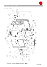
Page 44: ...1000870 871 875 878 879 880 887 MIX Service Manual b Page 44 of 69 11 PART DIAGRAMS LISTS 11 1 Mix PB3 parts ...

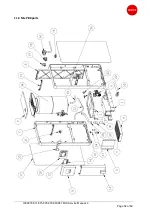
Page 45: ...1000870 871 875 878 879 880 887 MIX Service Manual b Page 45 of 69 11 1 Mix PB3 parts cont ...

Page 46: ...1000870 871 875 878 879 880 887 MIX Service Manual b Page 46 of 69 11 1 Mix PB3 parts cont ...

Page 47: ...1000870 871 875 878 879 880 887 MIX Service Manual b Page 47 of 69 11 1 Mix PB3 parts cont ...

Page 48: ...1000870 871 875 878 879 880 887 MIX Service Manual b Page 48 of 69 11 2 Mix T8 parts ...

Page 49: ...1000870 871 875 878 879 880 887 MIX Service Manual b Page 49 of 69 11 2 Mix T8 parts cont ...

Page 50: ...1000870 871 875 878 879 880 887 MIX Service Manual b Page 50 of 69 11 2 Mix T8 parts cont ...

Page 51: ...1000870 871 875 878 879 880 887 MIX Service Manual b Page 51 of 69 11 2 Mix T8 parts cont ...

Page 52: ...1000870 871 875 878 879 880 887 MIX Service Manual b Page 52 of 69 11 3 Mix PB8 parts ...

Page 53: ...1000870 871 875 878 879 880 887 MIX Service Manual b Page 53 of 69 11 3 Mix PB8 parts cont ...

Page 54: ...1000870 871 875 878 879 880 887 MIX Service Manual b Page 54 of 69 11 3 Mix PB8 parts cont ...

Page 55: ...1000870 871 875 878 879 880 887 MIX Service Manual b Page 55 of 69 11 3 Mix PB8 parts cont ...

Page 56: ...1000870 871 875 878 879 880 887 MIX Service Manual b Page 56 of 69 11 4 Mix UC3 parts ...

Page 57: ...1000870 871 875 878 879 880 887 MIX Service Manual b Page 57 of 69 11 4 Mix UC3 parts cont ...

Page 58: ...1000870 871 875 878 879 880 887 MIX Service Manual b Page 58 of 69 11 4 Mix UC3 parts cont ...

Page 59: ...1000870 871 875 878 879 880 887 MIX Service Manual b Page 59 of 69 11 4 Mix UC3 parts cont ...

Page 60: ...1000870 871 875 878 879 880 887 MIX Service Manual b Page 60 of 69 11 5 Mix UC8 parts cont ...

Page 61: ...1000870 871 875 878 879 880 887 MIX Service Manual b Page 61 of 69 11 5 Mix UC8 parts cont ...

Page 62: ...1000870 871 875 878 879 880 887 MIX Service Manual b Page 62 of 69 11 5 Mix UC8 parts cont ...

Page 63: ...1000870 871 875 878 879 880 887 MIX Service Manual b Page 63 of 69 11 5 Mix UC8 parts cont ...

Page 64: ...1000870 871 875 878 879 880 887 MIX Service Manual b Page 64 of 69 ...

Page 65: ...1000870 871 875 878 879 880 887 MIX Service Manual b Page 65 of 69 11 6 Mix Font 3 Button ...

Page 66: ...1000870 871 875 878 879 880 887 MIX Service Manual b Page 66 of 69 11 6 Mix Font 3 Button cont ...

Page 67: ...1000870 871 875 878 879 880 887 MIX Service Manual b Page 67 of 69 11 7 Mix Font 1 Button ...

Page 68: ...1000870 871 875 878 879 880 887 MIX Service Manual b Page 68 of 69 11 7 Mix Font 1 Button cont ...

Page 69: ...1000870 871 875 878 879 880 887 MIX Service Manual b Page 69 of 69 MARCO is an ISO9001 2000 Registered Company ...

Reviews: