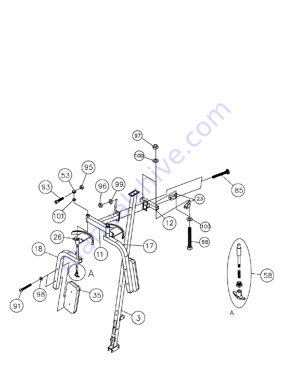
STEP 7 (See Diagram 7)
A.) Attach the Butterfly Support Frame (#11) to the front of Right Vertical Frame (#3). Attach
the Butterfly Pulley Support (#12) to the back of Right Vertical Frame. Align the holes and
secure them with two M10 x 2 ½” Carriage Bolts (#85), Ø ¾” Washers (#99), and M10
Aircraft Nuts (#96).
B.) Attach two Swivel Pulley Brackets (#23) to the Butterfly Pulley Support (#12). Secure each
Bracket with one M12 x 4 3/8” Hex Bolt (#88), two Ø1” Washers (#100), and one M12
Aircraft Nut (#97). Do not over tighten the nut and bolt. The brackets need to swivel.
C.) Insert the Axle on the Right Butterfly (#18) through a Butterfly Adjustment Frame (#26) into
the hole on the Butterfly Support Frame (#11). Secure it with one Ø1 ½” Washer (#101),
Lock Ring (#53), M6 x 1 ¼” Allen Bolt (#93), and M6 Aircraft Nut (#95).
D.) Thread a T-shaped Pull Pin (#58) through the hole on the Right Butterfly. Use the Pin to
adjust the Butterfly position.
E.) Attach a Butterfly Arm Pad (#35) to the Right Butterfly. Secure it with two M8 x 2 3/8” Allen
Bolts (#91) and Ø 5/8” Washers (#98).
F.) Repeat procedures C, D and E above to install the Left Butterfly.
13
Summary of Contents for GS 99
Page 4: ...HARDWARE PACK...
Page 5: ...3 HARDWARE PACK...
Page 6: ...4 HARDWARE PACK...
Page 11: ...DIAGRAM 4 10...
Page 16: ...CABLE LOOP DIAGRAM 15...
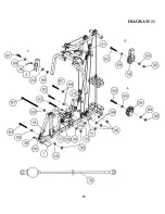
Page 20: ...DIAGRAM 11 19...
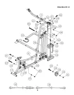
Page 22: ...DIAGRAM 12 21...
Page 27: ......


