STEP 14 (See Diagram 14)
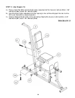
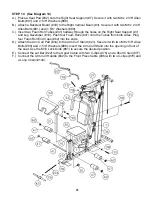
A.) Place a Seat Pad (#32) onto the Right Seat Support (#7). Secure it with two M8 x 2 3/8” Allen
Bolts (#91) and
∅
5/8” Washers (#98).
B.) Attach a Backrest Board (#33) to the Right Vertical Beam (#3). Secure it with two M8 x 2 3/8”
Allen Bolts (#91) and
∅
5/8” Washers (#98).
C.) Insert two Foam Roll Tubes (#41) halfway through the holes on the Right Seat Support (#7)
and Leg Developer (#19). Push four Foam Rolls (#47) onto the Tubes from both sides. Plug
four Foam Roll End Caps (#62) into the ends.
D.) Attach the Arm Curl Pad (#34) to the Arm Curl Stand (#21). Secure it with two M8 x 5/8” Allen
Bolts (#90) and
∅
5/8” Washers (#98). Insert the Arm Curl Stand into the opening in front of
the seat. Use the M18 Lock Knob (#61) to secure the desired position.
E.) Connect the Lat Bar (#22) to the Upper Cable with two C-clips (#78) and a Short Chain (#77).
F.) Connect the Arm Curl Handle (#42) to the Front Press Cable (#36) with two C-clips (#78) and
a Long Chain (#104).
23
Summary of Contents for GS 99
Page 4: ...HARDWARE PACK...
Page 5: ...3 HARDWARE PACK...
Page 6: ...4 HARDWARE PACK...
Page 11: ...DIAGRAM 4 10...
Page 16: ...CABLE LOOP DIAGRAM 15...
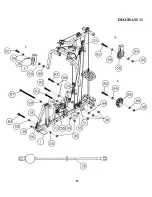
Page 20: ...DIAGRAM 11 19...
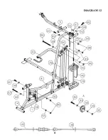
Page 22: ...DIAGRAM 12 21...
Page 27: ......


