background image


ASSEMBLY INSTRUCTION 


STEP 1 

Attach the front and rear stabilizer (38 & 29) to the main frame (31), tighten with four 
carriage bolts (39), curve washer (3) and acorn nut (4).   


STEP 2


Take the handlebar post (44) and connect the upper sensor wire (32) to the lower sensor 
wire (51). 

Ensure the Tension Control Knob is set to number 8.

 Connect the upper 

tension cable (62) to the lower tension cable (50). 

Please see the next page for a detailed 

description of this part of the assembly.

 Insert the handlebar post (44) into the main 

frame (31) and secure into position using 4 allen head bolts (49) and curved washers (3). 

Do not fully tighten the allen bolts at this stage. 


44 


7

Summary of Contents for Marcy ER5000D

Page 1: ...ER5000D Escalade International Limited Pleasant Road Penllergaer Swansea SA4 9GE Tel 00 44 1792 222 550 Fax 00 44 1792 895 781 www escaladesports co uk info escaladesports co uk ...

Page 2: ...ling and Tension Control 11 Computer Instructions 13 Exercise Instructions 15 Fault Finding Chart 16 Exploded Diagram 17 Parts List 18 Additional Information Care Maintenance 19 Limited Warranty 20 Supplied by Escalade International Ltd Pleasant Road Penllergaer Swansea SA4 9GE Tel 00 44 1792 222550 Fax 00 44 1792 895781 www escaladesports co uk 2 ...

Page 3: ...use the Elliptical their physical mental development and above all temperament should be taken into account Constant supervision is therefore needed 6 Position the Elliptical on a clear levelled surface which is clear of all obstacles as not to restrict movement whilst exercising DO NOT use the Elliptical near water or outdoors 7 Exercise equipment has moving parts In the interest of safety keep o...

Page 4: ...8 Flat washer 30mm diameter 2 9 Plastic washer 2 10 Flat washer 19mm diameter 2 17 Wavy washer 2 39 Carriage bolt M8 73L 4 49 Screw M8 16 4 Allen key S6 2 Allen key S5 1 Allen Wrench 10 13 19 1 Please note that some items of hardware may already be pre assembled onto your elliptical 4 ...

Page 5: ...IZER DES Q TY 1 1 2 1 2 1 2 1 2 1 No 27 No 34L No 34R No 40 No 41 No 31 No 2 No 6 No 38 No 29 No 44 PART No DESCRIPTION Q TY No 31 MAIN FRAME 1 No 44 FRONT POST 1 No 27 PEDAL ARM 2 No 41 COMPUTER 1 No 6 LOW HANDLEBAR 2 No 29 REAR STABILIZER 1 No 34 FEDAL R L 2 No 40 AXLE FOR HANKLEBAR 1 LEFT RIGHT UPPER HANDLEBAR No 2 2 No 38 FRONT STABILIZER 1 Above described parts are all the parts you need to a...

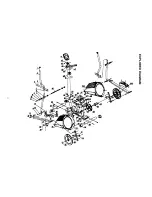
Page 6: ...EXPLODED ASSEMBLY DIAGRAM 6 ...

Page 7: ...nsor wire 32 to the lower sensor wire 51 Ensure the Tension Control Knob is set to number 8 Connect the upper tension cable 62 to the lower tension cable 50 Please see the next page for a detailed description of this part of the assembly Insert the handlebar post 44 into the main frame 31 and secure into position using 4 allen head bolts 49 and curved washers 3 Do not fully tighten the allen bolts...

Page 8: ...Upper Tension Connector in between the opening on the wire holder on the Lower Tension Connector Pull the Upper Tension Connector backward and slide the wire through the slot on the bracket Drop the Connector down so the fitting sits firmly on top of the bracket 8 ...

Page 9: ... 8 plastic washer 9 flat washer 10 and allen head bolt with blue dot 11 Repeat this procedure for the right handlebar Do not fully tighten the allen head bolts at this stage STEP 4 Assemble the left and right movable handlebars upper 2 onto the movable handlebars previously assembled and secure into position using four carriage bolts 5 curved washers 4 and acorn nuts 4 9 ...

Page 10: ...left rotation disk and secure into position using one wavy washer 17 and allen head bolt with blue dot 11 Insert the steel spacer 14 into the end on the left lower movable arm Connect the left pedal arm to the left lower movable arm using one bolt 16 flat washer 10 and nylon lock nut 12 Repeat the above procedure for the right hand side and tighten any hardware previously assembled 10 ...

Page 11: ... computer 41 Slide the computer onto the top of the handlebar stem ensuring the loose wires are inserted into the top of the stem and secure into position using two screws 43 PLEASE ENSURE THAT ALL NUTS AND BOLTS ARE SECURE BEFORE USE TRANSPORT LEVELLING AND TENSION CONTROL TRANSPORT 11 ...

Page 12: ...LEVELLING TENSION CONTROL 12 Increase Decrease ...

Page 13: ...ch time Display switches every 6 seconds 2 Time Automatically accumulate workout time when starting exercise 0 00 99 59 minutes 3 Speed Display current speed during workout time 0 0 99 9 KM HR 4 Distance Automatically accumulate workout distance when starting exercise 0 00 99 99 K M 5 Calories Automatically accumulate calories amount consumed when starting exercise 0 9999 6 Pulse Displays your cur...

Page 14: ...uipped with a Recovery Feature This special feature can help you to understand your heart rate recovery status after each workout Press the Recovery button after your entire workout program Place both hands on the pulse sensor the time will display one minute 00 60 and count down The computer will monitor your heart rate during this one minute and display your heart rate recovery status after the ...

Page 15: ... exercises as shown below Each stretch should be held for approximately 30 seconds do not force or jerk your muscles into a stretch if it hurts STOP INNER THIGH FORWARD BENDS CALF ACHILLES SIDE BENDS OUTER THIGH 2 The Exercise Phase This is the stage where you put the effort in After regular use the muscles in your legs will become more flexible It is very important to maintain a steady tempo thro...

Page 16: ... exercise phase you should increase resistance making your legs work harder You will have to reduce your speed to keep your heart rate in the target zone WEIGHT LOSS The important factor here is the amount of effort you put in The harder and longer you work the more calories you will burn Effectively this is the same as if you were training to improve your fitness the difference is the goal FAULT ...

Page 17: ...EXPLODED DIAGRAM 17 ...

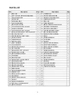
Page 18: ...UBE END CAP 2 55 FLYWHEEL 1 16 M8 55mm BOLT 2 56 SCREW 2 17 WAVY WASHER 2 57 ZIP SET FOR FLYWHEEL 2 18 FLAT WASHER 4 58 AXIS FOR FLYWHEEL 1 19 M6 NYLON LOCK NUT 4 59 BUSH FOR IDLE WHEEL 1 20 NYLON BUSH 4 60 IDLE WHEEL 1 21 PEDAL ARM LEFT RIGHT 2 61 6900ZZ BEARING 2 22 SCREW FOR COVER 6 62 UPPER TENSION CABLE 1 23 HEXAGON M8 SCREW 2 63 M8 HEXAGON SCREW 3 24 TURNDISK 2 64 AXIS FOR BIG PULLEY 1 25 DI...

Page 19: ...ation you are responsible for the appropriate disposal of your Elliptical to a recognised public collection facility CARE AND MAINTENANCE 1 Inspect and tighten all parts before using the elliptical 2 The elliptical can be cleaned using a damp cloth and mild non abrasive detergent DO NOT use solvents 3 Examine the elliptical regularly for signs of damage or wear 4 Failure to examine the elliptical ...

Page 20: ...sponsible or liable for indirect special or consequential damages arising out of or in connection with the use or performance of the product or other damages with respect to any economic loss loss of property loss of revenues or profits loss of enjoyments or use costs of removal installation or other consequential damages or whatsoever natures The warranty extended hereunder is in lieu of any and ...

Reviews: