V12-CE SETUP MANUAL
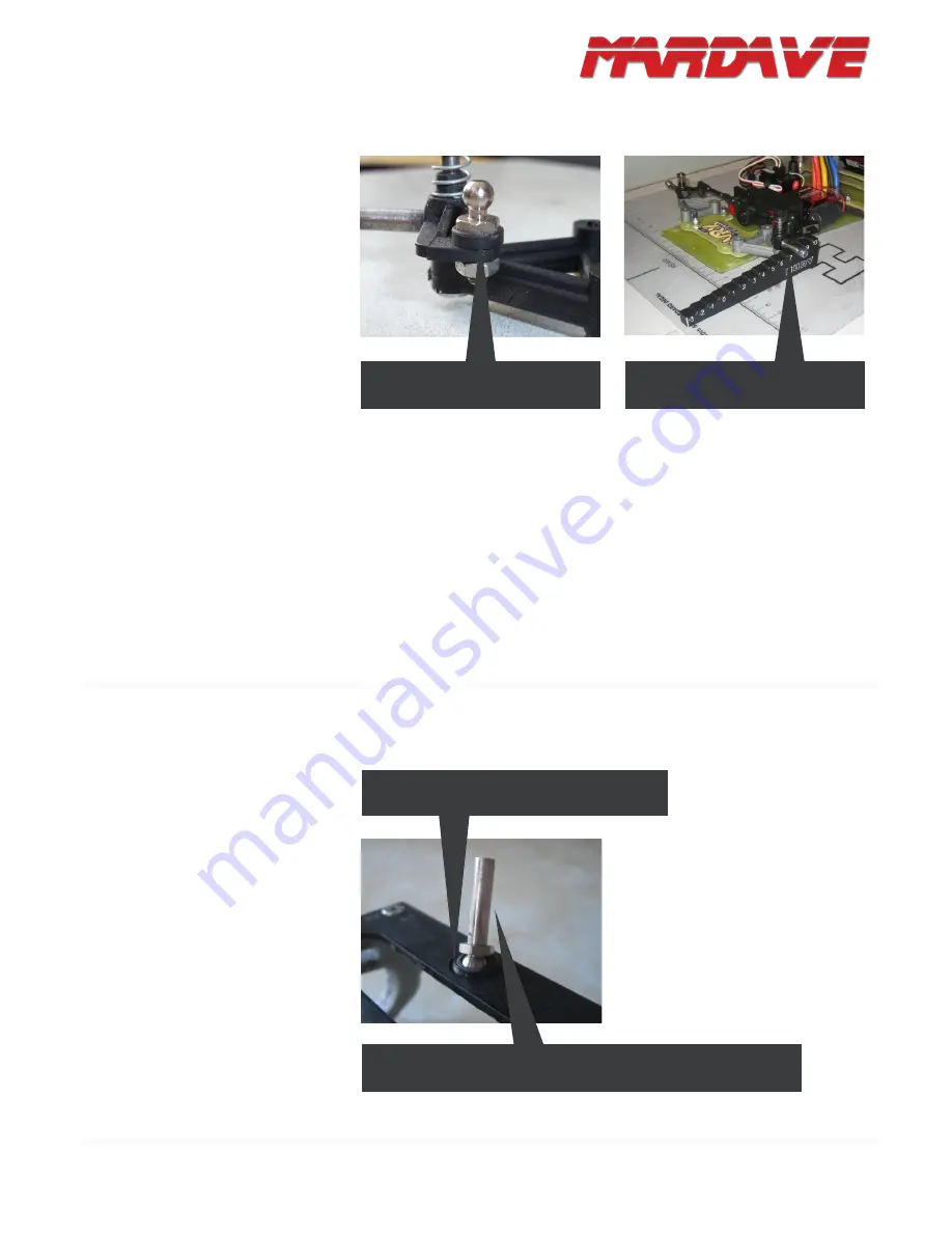
The steering system is easier - as-
semble all the parts and make sure
they all move freely. Add a 2mm
shim under the balls on the steering
arm (and use the bottom holes in
the servo saver) to get the steering
track rods as horizontal as possible
and minimize bump steer.
Lastly, make sure that the wish-
bones are seated level. Some-
times they can sit unevenly (this
can happen if any mould flashing
is not trimmed off the wishbone
mounts or steering blocks during
the build, or from racing impacts).
To check the wishbones, put the
chassis on a flat surface, centre
the steering and measure the
clearance of the stub axels off the
ground. Left and right sides must
be identical. If they are not, check
for mould flashing and trim it, check
that kingpins and stub axels are
straight and replace any defective
parts.
2.C. FRONT END
“Ride Height” of left and right stub
axels must be identical.
Approx 2mm of spacers under the
pivot ball to eliminate bump steer.
This is almost identical to all other
V12 kits, the only difference is the
damper tube. Assemble the pod
and add the damper tube’s ball
stud, axel bearings and diff. Some-
times the rear pod’s pivot ball can
be stiff when fitted in its hole in the
pod base plate. This is not good.
It is wise to give the ball a light rub
down by spinning it up in a drill and
polishing it with 400 wet/dry – this
will give a smoother movement, but
be careful not to make it so small
that you get any slop!
3. REAR END
If the rear pivot ball is tight in the cup, remove
it and sand it smooth with wet and dry paper.
This pivot ball has had a rear guide pin added to it via a grub screw.
The ball can rotate freely in the cup with just the weight of the pin.


