13
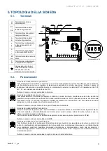
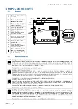
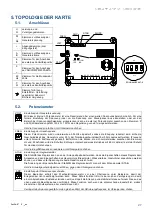
5. CARD LAYOUT
5.1.
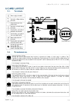
Terminals
U
N
Power supply terminals
S1
…
S6
Generator voltage sensing
terminals
+
-
Output terminals (to the
exciter field)
A
B
Generator current sensing
terminals
6
8
Terminals for connection to
external control device
9
-
+
Terminals for connection to
Varicomp M40FA621A
60
Hz
60Hz mode selection
terminals
P
Q
Terminals for connection to
external potentiometer
Connection to ground for
internal EMI filter -
Connection to ground of
shield of shielded cables
5.2.
Potentiometers
VOLT
MAX
MIN
Setup of generator voltage.
Normally the internal potentiometer VOLT permits to adjuste the voltage in a wide range; to obtain a finer
possibility of voltage setting or to adjust the voltage from the control panel, or in order to limit the voltage range, an
external potentiometer can be connected to the terminals P and Q (resistance about 100 k
Ω, 1 W, for a voltage
regulation of ±5%).
Turn clockwise to increase voltage
FREQ
MAX
MIN
Setup of the Corner Frequency.
It is usually set at the factory in order to reduce the excitation when speed becomes lower than 90% of rated
speed at 50 Hz (frequency lower than 45 Hz, or corner frequency). By removing the bridge which normally shorts
the terminals Hz and 60, the speed protection operates properly for 60 Hz operation mode.
Turn clockwise to decrease the frequency threshold
STAB
MAX
MIN
Setup of regulation stability.
The regulation can be set on the field to adapt it to the characteristics of the plant and the driving engine (diesel
engine, water turbine, gas turbine) in order to obtain the best voltage response. To change the stability
characteristics of the regulator, the potentiometer STAB must be adjusted.
Turn clockwise to increase the stability
AMP
MAX
MIN
Setup of the overexcitation threshold.
That limiter permits to protect the generator in case of over excitation due to load conditions that could cause the
rotor damage. Even if correctly set, this function does not substitute external systems protections, it is only a
completing device.
Turn clockwise to increase the limitation intervention threshold
SLOPE
MAX
MIN
Setup of the low speed protection characteristic slope
.
With the micro-switch 4 OFF, this potentiometer allows to increase or decrease the under-speed ramp slope, and
set the voltage droop for a fixed reduced speed.
Turn clockwise to decrease the voltage dip
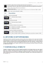
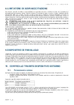
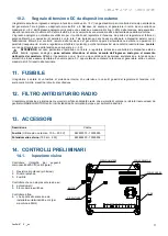
S6 S5 S4 S3 S2 S1
9
-
+
N
U
-
+
PAR
6
8
B
A
P
Q
60
Hz
VOLT
FREQ
AMP
STAB
SLOPE
ON
OFF
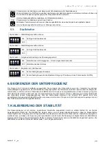
Micro-switches 1-4
2
4
1
3
YELLOW
LED
RED
LED
F
U
S
E


