Check switch operation:
a. Loads have no voltage in “OFF” position
b. Loads have voltage in “ON” position
c. House loads only have voltage in “1 ON” position
Fit Actuator at
0, 90, 180, or
270 degrees
to suit cabling
OFF
ON
OFF
ON
OFF
ON
OFF
ON
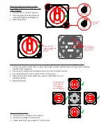
Replacement of Actuator (always remove, and replace the Actuator with knob in the “OFF” position)
1. Check that switch contact shaft (on base) hasn’t been rotated, and that arrow on base shaft is pointing
towards “OFF” engraving
2. Ensure that that light grey fastening screws are in the “unlocked” position
3. Ensure that Actuator knob is rotated to the “OFF” position
4. Note that Actuator can be fitted at any position 0/90/180/270 to suit
electrical cabling
5. Replace Actuator
Removal of Actuator (always remove,
and replace the Actuator with knob in the
“OFF” position):
1. Ensure knob is on “OFF” position
2. Undo light grey fastening screws by
rotating 45 degrees anticlockwise
3. Remove Actuator
UNLOCKED
LOCKED
Ensure dots align
for “LOCKED”
position
OFF
ON
Always remove &
replace Actuator with
knob in the "OFF"
position
OFF
ON
1
2
Off Position For
Switch Base, When
Arrows On Shaft
Points At “OFF”


