background image

Plug & Test

TM

 Smart Force & Torque Sensors 


User’s Guide 


1


Thank you… 
 

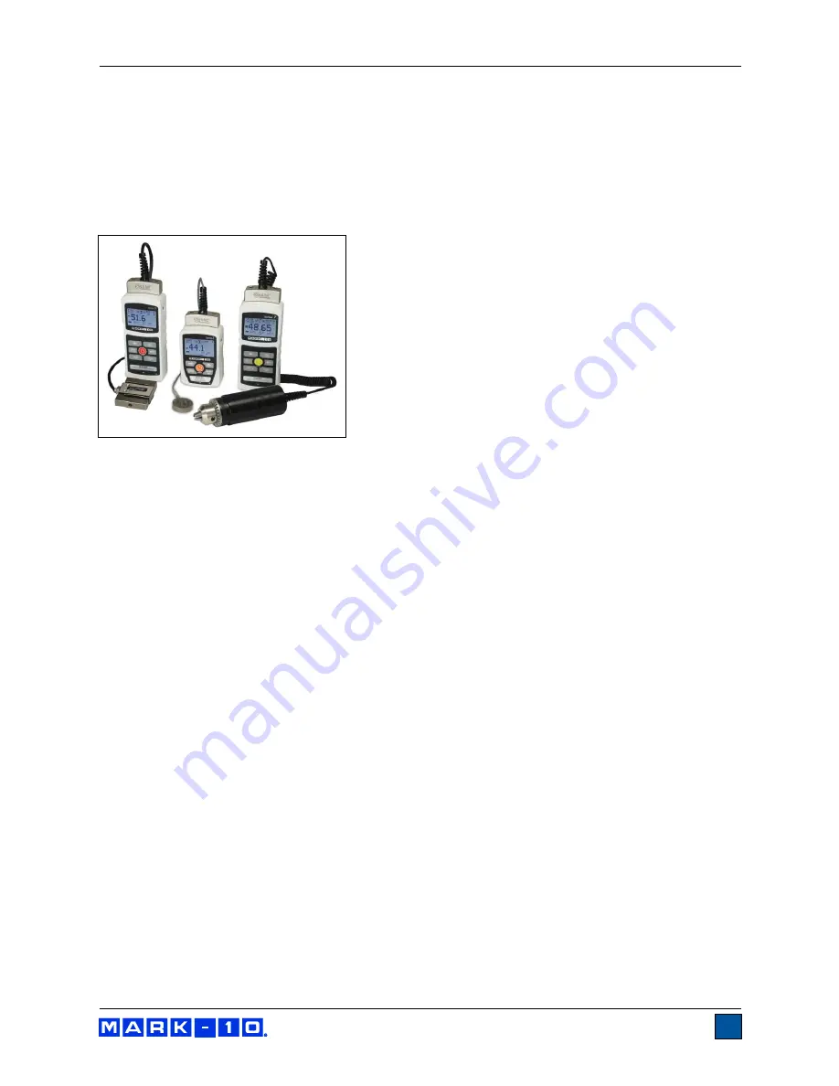
Thank you for purchasing a Mark-10 Plug & Test

TM

 remote sensor, designed for use with Mark-10 models 

7i, 5i and 3i force/torque indicators. 
 
With proper usage, we are confident that you will get many years of great service with this product. Mark-
10 sensors are ruggedly built for many years of service in laboratory and industrial environments.  

  
This  User’s  Guide  provides  setup,  safety,  and  operation 
instructions  for  each  individual  sensor  series.  Instructions  for 
using  models  5i  and  3i  indicators  are  available  in  their 
respective user’s guides. For additional information or answers 
to  your  questions,  please  do  not  hesitate  to  contact  us.  Our 
technical  support  and  engineering  teams  are  eager  to  assist 
you.  
  

Before  use,  each  person  who  is  to  use  Mark-10  sensors 
and  indicators  should  be  fully  trained  in  appropriate 
operation and safety procedures. 


TABLE OF CONTENTS 


OVERVIEW

 ..................................................... 

…2 

SAFETY / PROPER USAGE

 ..............................3 

SETUP

 ................................................................4 

SERIES R01 FORCE SENSORS

 .......................5 

SERIES R02 FORCE SENSORS

 .......................6 

SERIES R03 FORCE SENSORS

 .......................7 

SERIES R04 FORCE SENSORS

 .......................8 

SERIES R05 FORCE SENSORS

 .......................9 

SERIES R06 FORCE SENSORS

 .................... 10 

SERIES R50 TORQUE SENSORS

 ................. 11 

SERIES R51 TORQUE SENSORS

 ................. 13 

SERIES R52 TORQUE SENSORS

 ................. 15 

SERIES R53 TORQUE SENSORS

 ................. 16 

SERIES R54 TORQUE SENSORS

 ................. 17 

SERIES R55 TORQUE SENSORS

 ................. 18 


Summary of Contents for 3i

Page 1: ...SMART FORCE AND TORQUE SENSORS User s Guide ...

Page 2: ...ators are available in their respective user s guides For additional information or answers to your questions please do not hesitate to contact us Our technical support and engineering teams are eager to assist you Before use each person who is to use Mark 10 sensors and indicators should be fully trained in appropriate operation and safety procedures TABLE OF CONTENTS OVERVIEW 2 SAFETY PROPER USA...

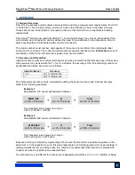
Page 3: ...ccuracy of the system Since sensors may be used with the 7i 5i or 3i indicators the accuracy of the indicator being used must be identified and taken into account as follows Indicator Model Accuracy 7i 5i 0 1 of full scale 3i 0 2 of full scale The total system accuracy can be calculated by adding the sensor accuracy and indicator accuracy Refer to the following examples Example 1 Model MR01 100 se...

Page 4: ... the sample being tested before initiating a test A risk assessment should be carried out beforehand to ensure that all safety measures have been addressed and implemented 8 Typical materials able to be tested include many manufactured items such as springs electronic components fasteners caps films mechanical assemblies and many others Items that should not be used with the sensor include potenti...

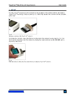
Page 5: ...onnector will lock into place with a click Fig 3 1 Appropriate orientation of the Plug TestTM connector To release the connector press both buttons on either side of the indicator housing see Fig 3 2 Pull the connector completely out of the indicator by holding the curved aluminum section DO NOT pull on the cable or strain relief Fig 3 2 Press both buttons on either side of the indicator housing t...

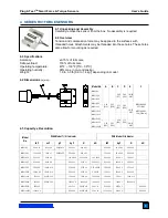
Page 6: ... 20 50 x 0 02 500 x 0 2 100 x 0 1 50 x 0 05 500 x 0 5 MR01 200 200 x 0 1 3200 x 2 100 x 0 05 1000 x 0 5 1 x 0 0005 200 x 0 2 100 x 0 1 1000 x 1 MR01 500 500 x 0 2 8000 x 5 250 x 0 1 2500 x 1 2 5 x 0 001 500 x 0 5 250 x 0 2 2500 x 2 MR01 750 750 x 0 5 12000 x 10 375 x 0 2 3750 x 2 3 75 x 0 002 750 x 0 5 375 x 0 2 3750 x 2 MR01 1000 1000 x 0 5 16000 x 10 500 x 0 2 5000 x 2 5 x 0 002 1000 x 1 500 x 0...

Page 7: ... ØB C D ØE F ØG MR02 100 MR02 2000 1 25 31 8 0 32 8 1 0 05 1 3 0 39 9 9 1 0 25 4 0 83 21 1 MR02 5000 MR02 10000 1 50 38 1 0 43 10 9 0 07 1 8 0 62 15 8 1 25 31 8 0 25 6 4 1 08 27 4 5 5 Capacity x Resolution Model No With Model 7i 5i Indicator With Model 3i Indicator lbF ozF gF kgF N kN lbF kgF N kN MR02 100 100 x 0 05 1600 x 1 50000 x 20 50 x 0 02 500 x 0 2 100 x 0 1 50 x 0 05 500 x 0 5 MR02 200 20...

Page 8: ... Capacity x Resolution Model No With Model 7i 5i Indicator With Model 3i Indicator lbF ozF gF kgF N mN lbF gF kgF N MR03 025 0 25 x 0 0001 4 x 0 002 100 x 0 05 1 x 0 0005 1000 x 0 5 0 25 x 0 0002 100 x 0 1 1 x 0 001 MR03 05 0 5 x 0 0002 8 x 0 005 250 x 0 1 2 5 x 0 001 2500 x 1 0 5 x 0 0005 250 x 0 2 2 5 x 0 002 MR03 2 2 x 0 001 32 x 0 02 1000 x 0 5 1 x 0 0005 10 x 0 005 2 x 0 002 1 x 0 001 10 x 0 ...

Page 9: ...ity x Resolution Model No With Model 7i 5i Indicator With Model 3i Indicator lbF ozF gF kgF N mN lbF gF kgF N MR04 025 0 25 x 0 0001 4 x 0 002 100 x 0 05 1 x 0 0005 1000 x 0 5 0 25 x 0 0002 100 x 0 1 1 x 0 001 MR04 05 0 5 x 0 0002 8 x 0 005 250 x 0 1 2 5 x 0 001 2500 x 1 0 5 x 0 0005 250 x 0 2 2 5 x 0 002 MR04 2 2 x 0 001 32 x 0 02 1000 x 0 5 1 x 0 0005 10 x 0 005 2 x 0 002 1 x 0 001 10 x 0 01 MR0...

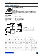
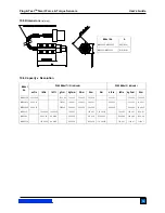
Page 10: ...lied to the surface with threaded hole Attachments may be threaded into these holes Finger tighten only 8 3 Specifications Accuracy 0 15 of full scale Safe overload 150 of full scale Operating temperature 40ºF 100ºF 5ºC 38ºC Operating humidity 96 max non condensing Weight 2 lb 0 9 kg 8 4 Dimensions in mm 8 5 Capacity x Resolution Model No With Model 7i 5i Indicator With Model 3i Indicator lbF ozF ...

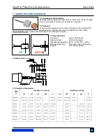
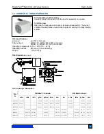
Page 11: ...round the cam shaft Then insert the terminal lead in the slot on the upper grip Begin to compress and release the handles slowly Tension force values will be displayed on the indicator After the test is complete remove any debris from the upper grip assembly and depress the button on the cam shaft to remove the wire 9 3 Specifications Accuracy 0 5 of full scale Safe overload 150 of full scale Oper...

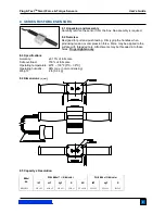
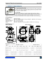
Page 12: ...ions Accuracy 0 35 of full scale Safe overload MR50 10Z MR50 50Z 300 of full scale MR50 12 MR50 100 150 of full scale Chuck opening range MR50 10Z MR50 50Z 0 062 0 375 in 1 6 9 5 mm MR50 12 MR50 100 0 078 0 5 in 2 0 12 7 mm Operating temperature 40ºF 100ºF 5ºC 38ºC Operating humidity 96 max non condensing Weight From 1 4 lb 0 6 kg 10 4 Calibration Calibration should be performed in a vertical orie...

Page 13: ...R50 20Z 20 x 0 01 1400 x 1 14 x 0 01 140 x 0 1 14 x 0 01 20 x 0 02 14 x 0 01 14 x 0 01 MR50 50Z 50 x 0 02 3600 x 2 36 x 0 02 350 x 0 2 35 x 0 02 50 x 0 05 36 x 0 05 35 x 0 05 MR50 12 12 x 0 005 1 x 0 0005 140 x 0 1 135 x 0 1 1 35 x 0 001 12 x 0 01 140 x 0 1 135 x 0 1 MR50 50 50 x 0 02 4 x 0 002 580 x 0 5 570 x 0 5 5 7 x 0 005 50 x 0 05 580 x 0 5 570 x 0 5 MR50 100 100 x 0 05 8 x 0 005 1150 x 0 5 1...

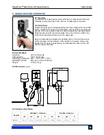
Page 14: ...re should be taken when handling low capacity models 11 3 Specifications Accuracy 0 2 of full scale Safe overload MR50 10Z MR50 50Z 300 of full scale MR50 12 MR50 100 150 of full scale Chuck opening range MR50 10Z MR50 50Z 0 062 0 375 in 1 6 9 5 mm MR50 12 MR50 100 0 078 0 5 in 2 0 12 7 mm Operating temperature 40ºF 100ºF 5ºC 38ºC Operating humidity 96 max non condensing Weight From 1 4 lb 0 6 kg ...

Page 15: ... 700 x 0 5 7 x 0 005 70 x 0 05 7 x 0 005 10 x 0 01 7 x 0 005 7 x 0 005 MR51 20Z 20 x 0 01 1400 x 1 14 x 0 01 140 x 0 1 14 x 0 01 20 x 0 02 14 x 0 01 14 x 0 01 MR51 50Z 50 x 0 02 3600 x 2 36 x 0 02 350 x 0 2 35 x 0 02 50 x 0 05 36 x 0 05 35 x 0 05 MR51 12 12 x 0 005 1 x 0 0005 140 x 0 1 135 x 0 1 1 35 x 0 001 12 x 0 01 140 x 0 1 135 x 0 1 MR51 50 50 x 0 02 4 x 0 002 580 x 0 5 570 x 0 5 5 7 x 0 005 ...

Page 16: ...non condensing Weight 1 2 lb 0 5 kg 12 4 Dimensions in mm 12 5 Capacity x Resolution Model No With Model 7i 5i indicator With Model 3i indicator ozFin lbFin lbFft gFcm kgFmm Nmm Ncm Nm ozFin lbFin kgFmm Ncm MR52 10Z 10 x 0 005 700 x 0 5 7 x 0 005 70 x 0 05 7 x 0 005 10 x 0 01 7 x 0 005 7 x 0 005 MR52 20Z 20 x 0 01 1400 x 1 14 x 0 01 140 x 0 1 14 x 0 01 20 x 0 02 14 x 0 01 14 x 0 01 MR52 50Z 50 x 0...

Page 17: ...Z 300 of full scale MR53 12 MR53 100 150 of full scale Operating temperature 40ºF 100ºF 5ºC 38ºC Operating humidity 96 max non condensing Weight MR53 10Z MR53 50Z 2 2 lb 1 0 kg MR53 12 MR53 100 5 4 lb 2 5 kg 13 4 Dimensions in mm MR53 10Z MR53 50Z MR53 12 MR53 100 13 5 Capacity x Resolution Model No With Model 7i 5i indicator With Model 3i indicator ozFin lbFin lbFft gFcm kgFmm Nmm Ncm Nm ozFin lb...

Page 18: ... lbFft kgFmm Ncm Nm lbFin kgFmm Ncm MR54 20 20 x 0 02 1 5 x 0 002 230 x 0 2 220 x 0 2 2 x 0 002 20 x 0 02 230 x 0 2 220 x 0 2 MR54 50 50 x 0 05 4 x 0 005 580 x 0 5 570 x 0 5 5 7 x 0 005 50 x 0 05 580 x 0 5 570 x 0 5 MR54 100 100 x 0 1 8 x 0 01 1150 x 1 1150 x 1 11 5 x 0 01 100 x 0 1 1150 x 1 1150 x 1 MR54 200 200 x 0 2 16 x 0 02 2300 x 2 2200 x 2 22 x 0 02 200 x 0 2 2300 x 2 2200 x 2 MR54 400 400 ...

Page 19: ...lbFin kgFmm Ncm MR55 20 20 x 0 02 1 5 x 0 002 230 x 0 2 220 x 0 2 2 x 0 002 20 x 0 02 230 x 0 2 220 x 0 2 MR55 50 50 x 0 05 4 x 0 005 580 x 0 5 570 x 0 5 5 7 x 0 005 50 x 0 05 580 x 0 5 570 x 0 5 MR55 100 100 x 0 1 8 x 0 01 1150 x 1 1150 x 1 11 5 x 0 01 100 x 0 1 1150 x 1 1150 x 1 MR55 200 200 x 0 2 16 x 0 02 2300 x 2 2200 x 2 22 x 0 02 200 x 0 2 2300 x 2 2200 x 2 MR55 400 400 x 0 5 32 x 0 05 4600...

Page 20: ...In addition to our standard line of products we can provide modifications and custom designs for OEM applications Our engineering team is eager to satisfy any special requirements Please contact us for further information or suggestions for improvement Force and torque measurement engineered better Mark 10 Corporation 11 Dixon Avenue Copiague NY 11726 USA 1 888 MARK TEN Tel 631 842 9200 Fax 631 84...

Reviews: