background image

Series BG

8

CAL - Calibration. See Section 10.

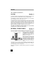
FILTERS

For maximum flexibility in noise suppression and peak capturing ability of the instru-
ment, there are two types of filters available to the user: analog and digital.

The analog filter is a simple RC network with a cutoff frequency of 2.5 Hz and attenu-
ation of 20 dB/decade. It can be either turned on or off.

The digital filter utilizes the moving average technique in which consecutive readings
are "pushed" through a buffer and the displayed reading is the average of the buffer
contents. By varying the length of the buffer, a variable smoothing effect can be
achieved. The BG is equipped with a buffer which can hold up to eight readings. The
number of readings to be averaged can be set to 1,2,4 or 8. The selection of 1 will
disable the filter since the average of a single value is the value itself.

The analog and the digital filters should be disabled or set to their minimum
acceptable values for highest peak capture speed.

EXTERNAL TRIGGER MODE

This mode of operation is useful for measuring electrical contact activation force as
well as synchronization of multiple instruments for a "snap-shot" view of applied

forces. When this mode is enabled through
the configuration menu (see Section 3),
the MODE key will sequence through an
additional state which is indicated by the
flashing "C" or "T" indicator.

When in this mode, the instrument stops
updating the display when the trigger sig-
nal is applied. It is possible to capture the
reading with a normally open contact (high
to low transition of the trigger signal) or a
normally closed contact (low to high tran-
sition).

The display will show the captured reading until ZERO or CLEAR is pressed if the
"edge" mode is set. The "level" mode provides for the display to hold the reading only
until the trigger signal returns to its original state.

Please refer to the diagram for connection details and to Section 3 for configuration
information.

USER - SUPPLIED

SWITCH UNDER TEST

47K

+5V

GND

TRIG

3

5

GAUGE

Section 4

Section 5

Summary of Contents for BG012

Page 1: ...Series BG DIGITALFORCE GAUGES User s Guide...

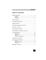
Page 2: ...ECTION 4 6 EXTERNAL TRIGGER MODE SECTION 5 6 SET POINTS SECTION 6 7 AVERAGE MODE SECTION 7 7 GAUGE CONTROL LANGUAGE SECTION 8 8 OUTPUTS SECTION 9 10 RS 232 10 Mitutoyo BCD 10 Analog 10 I O connector p...

Page 3: ...dings DATA Initiates a data transmission sequence if equipped with the communication option MODE ADVANCE Switches the display between normal and peak modes of operation CLEAR ESCAPE Clears peak readin...

Page 4: ...a steady LO BAT indicating approximately one hour of charge remaining The second level is indicated by a flashing LO BAT At the third level the whole display except the LO BAT indicator will flash for...

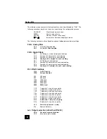
Page 5: ...es for each reading FP 1 No filtering of peak readings FP 2 Average of 2 samples for each peak reading FP 4 Average of 4 samples for each peak reading FP 8 Average of 8 samples for each peak reading 2...

Page 6: ...itted 8 Every 8th sample transmitted 16 Every 16th sample transmitted 32 Every 32nd sample transmitted 64 Every 64th sample transmitted 128 Every 128th sample transmitted AoFF Automatic shutoff settin...

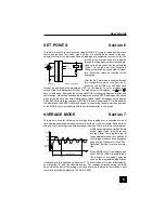
Page 7: ...or set to their minimum acceptable values for highest peak capture speed EXTERNAL TRIGGER MODE This mode of operation is useful for measuring electrical contact activation force as well as synchroniza...

Page 8: ...either case SP will appear on the display and the ENTER key may be used for re entering the set point change mode or the MODE key for proceeding with the normal operation of the gauge AVERAGE MODE Thi...

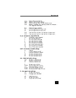
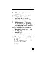
Page 9: ...Auto transmit every nth reading n 0 1 2 4 8 16 32 64 128 0 disabled LB Switch units to pounds KG Switch units to kilograms N Switch units to Newtons G Switch units grams ET Enable External trigger mo...

Page 10: ...ware version the last field shows the remaining battery power B0 full charge B3 minimum power All other fields show the status of settings and features using the same abbreviations as the commands to...

Page 11: ...ion to data collectors printers multiplexers or any other device capable of accepting Mitutoyo BCD data The transmission is initiated by the DATA key or by the receiving device see Section 3 for setti...

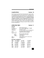
Page 12: ...ssing ESCAPE SPECIFICATIONS Section 11 General Accuracy 0 2 of full scale 1 count Tare capacity 110 of capacity Display shows at 110 Overload capacity 150 of capacity Display shows at 110 Sampling rat...

Page 13: ...nvironment or use other than intended will void this warranty This warranty is in lieu of all other warranties includ ing implied warranties of merchantability and fitness for an intended purpose In n...

Reviews: