background image

9

User's Guide

SET POINTS

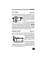
This feature is useful for tolerance checking (GO/NO GO) or alarm indication in process
control applications. Two limits, high and low, are specified and stored in the non-
volatile memory of the instrument and all readings are compared to these limits. The

results of the comparisons are indicated
through the three open-collector outputs pro-
vided on the 9-pin connector, thus providing
"under", "in range" and "over" signaling.
These outputs can be connected to indica-
tors, buzzers or relays as required for the
application.

After the Set Point mode is enabled through
the configuration menu (see Section 3),
pressing the MODE key will sequence

through an additional step indicated by "SP" on the display. To enter or change the
values of the set points press ENTER. The high set point is displayed. Use     and
keys to increase or decrease the value and MODE for changing between tension and
compression. When the desired value is displayed, press ENTER and repeat the above
steps for the low set point. After entering both values "donE" will appear on the display.
Press ENTER to store the changes or ESCAPE to quit. In either case "SP" will appear on
the display and the ENTER key may be used for re-entering the set point change mode
or the MODE key for proceeding with the normal operation of the gauge.

AVERAGE MODE

This mode is used for obtaining an average force reading over a specified period of
time. Applications include measurement of peel force, muscle strength, frictional force
and any other tests requiring time-averaged readings. There are three user-program-

mable parameters associated with this
mode: trigger force, initial delay and
average time. The programming of
these parameters and the enabling of
the Average mode are done during the
gauge setup. Please refer to the "Con-
figuration" section for more informa-
tion.

Press MODE until "A" is displayed and
then CLEAR or ZERO to begin testing.
The process of averaging begins as
soon as the programmed trigger force

is reached and is indicated by a flashing "A". The conclusion of the test is indicated by
an alternating "A" and the calculated value. The readings obtained during the initial
delay will not be part of the average, but the peak value is stored for later recall. A new
test may be started by pressing CLEAR or ZERO.

DELAY

AVERAGE TIME

TIME

FORCE

PEAK

AVE

TRIGGER

FORCE

USER - SUPPLIED

40 ma MAX

AS ABOVE

SAME

2N3904

GAUGE

9

8

5

GND

4

OUT

_

+

24V MAX

LOAD

Section 6

Section 7

AVG

Summary of Contents for BG012

Page 1: ...Series BG DIGITALFORCE GAUGES User s Guide...

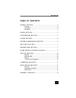
Page 2: ...ECTION 4 6 EXTERNAL TRIGGER MODE SECTION 5 6 SET POINTS SECTION 6 7 AVERAGE MODE SECTION 7 7 GAUGE CONTROL LANGUAGE SECTION 8 8 OUTPUTS SECTION 9 10 RS 232 10 Mitutoyo BCD 10 Analog 10 I O connector p...

Page 3: ...dings DATA Initiates a data transmission sequence if equipped with the communication option MODE ADVANCE Switches the display between normal and peak modes of operation CLEAR ESCAPE Clears peak readin...

Page 4: ...a steady LO BAT indicating approximately one hour of charge remaining The second level is indicated by a flashing LO BAT At the third level the whole display except the LO BAT indicator will flash for...

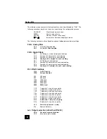
Page 5: ...es for each reading FP 1 No filtering of peak readings FP 2 Average of 2 samples for each peak reading FP 4 Average of 4 samples for each peak reading FP 8 Average of 8 samples for each peak reading 2...

Page 6: ...itted 8 Every 8th sample transmitted 16 Every 16th sample transmitted 32 Every 32nd sample transmitted 64 Every 64th sample transmitted 128 Every 128th sample transmitted AoFF Automatic shutoff settin...

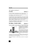
Page 7: ...or set to their minimum acceptable values for highest peak capture speed EXTERNAL TRIGGER MODE This mode of operation is useful for measuring electrical contact activation force as well as synchroniza...

Page 8: ...either case SP will appear on the display and the ENTER key may be used for re entering the set point change mode or the MODE key for proceeding with the normal operation of the gauge AVERAGE MODE Thi...

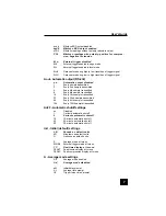
Page 9: ...Auto transmit every nth reading n 0 1 2 4 8 16 32 64 128 0 disabled LB Switch units to pounds KG Switch units to kilograms N Switch units to Newtons G Switch units grams ET Enable External trigger mo...

Page 10: ...ware version the last field shows the remaining battery power B0 full charge B3 minimum power All other fields show the status of settings and features using the same abbreviations as the commands to...

Page 11: ...ion to data collectors printers multiplexers or any other device capable of accepting Mitutoyo BCD data The transmission is initiated by the DATA key or by the receiving device see Section 3 for setti...

Page 12: ...ssing ESCAPE SPECIFICATIONS Section 11 General Accuracy 0 2 of full scale 1 count Tare capacity 110 of capacity Display shows at 110 Overload capacity 150 of capacity Display shows at 110 Sampling rat...

Page 13: ...nvironment or use other than intended will void this warranty This warranty is in lieu of all other warranties includ ing implied warranties of merchantability and fitness for an intended purpose In n...

Reviews: