background image

User’s Guide 


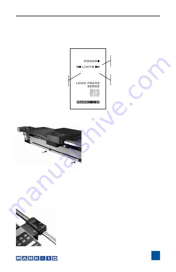
LEFT LIMIT 

Indicates a limit condition 

in compression. 

RIGHT LIMIT 

Indicates a limit condition in 
tension. 

POWER


Power is indicated by an 
illuminated indicator. 

Powering up 

Plug the power cord into the controller and the other end into a wall outlet. Then 
turn on power with the power switch (see Page 5). 
 

Reading the indicators 


Using the limit switches 

Limit switches are included to allow the 
operator to set travel limits during testing. 
This feature is particularly useful for spring 
testing, elongation testing, and other appli-
cations where stopping at a predetermined 
position is a requirement. 
 
The limit switches are located in the rear 
of the test stand. Their positions can be 
adjusted by loosening the thumbscrews 
(shown at left), sliding them to either side, 

and retightening. During testing, when a travel limit has been reached, an indi-
cator will be illuminated (see illustration above) and the crosshead movement 
will stop.  
 

About the digital travel display (optional) 

 
The travel display covers 12” of travel with a 5-digit display (0.0005” resolution) 

and a computer interface for automated data collection. 
Use cable P/N 09-1066 to output data to a PC. 
 
Complete instructions are provided in a separate user’s 
guide (included with the digital travel display). 

Summary of Contents for ESMH

Page 1: ...Model ESMH MOTORIZED FORCE MEASUREMENT TEST STAND User s Guide...

Page 2: ...ith specifications and dimensions For additional information or answers to your questions our technical support and engineering teams will be eager to help you Thank you again for your purchase and ha...

Page 3: ...rate user s guide 1 INTRODUCTION The ESMH motorized test stand is a horizontal force measurement tester designed to test up to 50 lb 250 N of tensile or compressive force The ESMH works in conjunction...

Page 4: ...seri ous injury or even death Ensure that the control unit is kept away from water or any other liquids at all times Make sure the electrical outlet powering the test stand has local earth ground 3 ho...

Page 5: ...the crosshead with the 5 16 screws Mounting grips and fixtures The ESMH includes a loading plate to which a grip or fixture may be mounted This plate can be mounted to the end of the stand with four...

Page 6: ...ng compressive force Release button to stop motion 3 RIGHT Press and hold to move the crosshead to the right producing tensile force Re lease button to stop motion 4 CONTROLLER CABLE Plug this cable i...

Page 7: ...er appli cations where stopping at a predetermined position is a requirement The limit switches are located in the rear of the test stand Their positions can be adjusted by loosening the thumbscrews s...

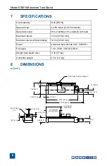
Page 8: ...2 mm Maximum travel w travel display 12 0 in 304 8 mm Power Universal input 80 240 VAC 50 60 Hz Fuse type 1 2 A 250V 3AG SLO BLO Weight test stand only 17 lb 7 7 kg Controller weight 2 7 lb 1 2 kg 2...

Page 9: ...odification abuse exposure to corrosive environment or use other than intended will void this warranty This warranty is in lieu of all other warranties including implied warran ties of merchantability...

Page 10: ...standard line of products we can provide modifications and custom designs for OEM applications Our engineering team is eager to satisfy any special requirements Please contact us for further informati...

Reviews: