background image

Series 4 Digital Force Gauges  

User’s Guide 


11


7   SET POINTS 

7.1 General Information 

Set points are useful for tolerance checking (pass/fail), triggering an external device such as a motorized 

test stand, or alarm indication in process control applications. Two limits, high and low, are specified and 

stored in the non-volatile memory of the instrument and the primary reading is compared to these limits. 

The results of the comparisons are indicated through the three outputs provided on the 15-pin connector, 

thus providing “under”, “in range”, and “over” signaling. These outputs can be connected to indicators, 

buzzers, or relays as required for the application. 

7.2 Configuration 

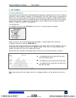
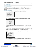
To configure set points, select 

Set Points

 from the menu. The screen appears as follows: 


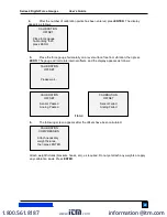
Either one, two, or none of the set points may be enabled. To toggle between the tension and 

compression directions, press the 

DIRECTION

 key. 

If two set points have been enabled, they are displayed in the upper left corner of the display. If only one 

set point has been enabled, the word “OFF” appears in place of the value. If no set points have been 

enabled, the upper left corner of the display will be blank.  
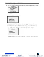
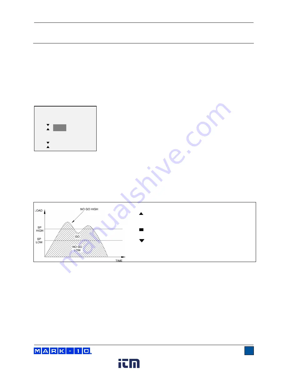
When set points are enabled, the following indicators are shown to the left of the primary reading: 


  – the displayed value is greater than the upper 

force limit (NO GO HIGH) 


  – the displayed value is between the limits (GO) 


 – the displayed value is less than the lower force 

limit (NO GO LOW) 


Note:

 Set point indicators and outputs reference the displayed reading, not necessarily the current live 

load. 


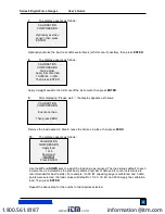
SET POINTS 

  Upper Disabled 

* Upper Enabled 


5.000


   Lower Disabled 

* Lower Enabled 
            3.500 

www.

.com

information@itm.com

1.800.561.8187

Summary of Contents for M4-012

Page 1: ...Series 4 DIGITAL FORCE GAUGES User s Guide www com information itm com 1 800 561 8187 ...

Page 2: ...rvice in laboratory and industrial environments This User s Guide provides setup safety and operation instructions Dimensions and specifications are also provided For additional information or answers to your questions please do not hesitate to contact us Our technical support and engineering teams are eager to assist you Before use each person who is to use the Series 4 force gauge should be full...

Page 3: ...nents that can present an exceedingly hazardous situation when acted upon by a force The following safety checks and procedures should be performed before and during operation 1 Never operate the gauge if there is any visible damage to the AC adapter or the gauge itself 2 Ensure that the gauge is kept away from water or any other electrically conductive liquids at all times 3 The gauge should be s...

Page 4: ...1 When battery life is greater than 75 the following indicator is present 2 When battery life is between 50 and 75 the following indicator is present 3 When battery life is between 25 and 50 the following indicator is present 4 When battery life is less than 25 the following indicator is present 5 When battery life drops to approximately 2 the indicator from step 4 will be flashing Several minutes...

Page 5: ...haft up Load cell shaft down 3 1 2 Mounting to a plate Proper mounting is important if attached to a fixture or test stand The round steel insert with a hole in the back of the housing is provided to withstand the load during a test A mating dowel pin should be used see illustration below Mounting plates on Mark 10 test stands include a dowel pin and clearance holes for the four threaded holes loc...

Page 6: ...out during a test preventing a potential safety risk to the operator and others in the vicinity If using a grip or fixture from a supplier other than Mark 10 ensure that it is constructed of suitably rugged materials and components Do not use jam nuts or tools to tighten grips or attachments onto the shaft Finger tighten only 3 2 Installing the USB driver If communicating via USB install the USB d...

Page 7: ...he midpoint of the graph Increasing to the right indicates compression load increasing to the left indicates tension load If set points are enabled triangular markers are displayed for visual convenience This indicator reflects the actual load which may not correspond to the primary reading depends on operating mode The ZERO key does not reset the load bar See Operating Modes section for details 5...

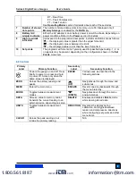
Page 8: ... configuration shown in the Set Points menu item 4 2 Controls Primary Label Primary Function Secondary Label Secondary Function Powers the gauge on and off Press briefly to power on press and hold to power off Active only when the home screen is displayed ENTER Various uses as described in the following sections ZERO Zeroes the primary reading and peaks UP Navigates up through the menu and sub men...

Page 9: ...t back to the sub menu item or press ESCAPE to revert back to the sub menu item without saving Press ESCAPE to revert one step back in the menu hierarchy until back into normal operating mode Refer to the following sections for details about setting up particular functions and parameters 5 OPERATING MODES Caution In any operating mode if the capacity of the instrument has been exceeded by more tha...

Page 10: ...ion of 1 will disable the filter since the average of a single value is the value itself To access digital filter settings select Filters from the menu The display appears as follows Two filters are available Current Reading Applies to the peak capture rate of the instrument Displayed Reading Applies to the primary reading on the display Available settings 1 2 4 8 16 32 64 128 256 512 1024 It is r...

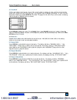
Page 11: ...n appears as follows Either one two or none of the set points may be enabled To toggle between the tension and compression directions press the DIRECTION key If two set points have been enabled they are displayed in the upper left corner of the display If only one set point has been enabled the word OFF appears in place of the value If no set points have been enabled the upper left corner of the d...

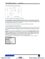
Page 12: ... points Readings may be stored viewed and output to an external device Individual or all data points may be deleted Statistics are calculated for the data in memory To enable memory storage select DATA Key from the menu then scroll to Memory Storage and press ENTER Then exit the menu In the home screen the data record number 00 appears below the primary reading Press DATA at any time to save the d...

Page 13: ... mean and standard deviation 8 3 Output Data Press ENTER to output data to an external device The display will show SENDING DATA then DATA SENT If there was a problem with communication the display will show DATA NOT SENT Saved data can be transmitted to a data collection program such as MESURTMgauge Refer to their respective user s guides for details 8 4 Output Statistics Press ENTER to output st...

Page 14: ... either included or excluded Output of data via the Mitutoyo output is possible however output of statistics is not Refer to the Communications and Outputs section for details Note Data is not retained while the gauge is powered off However the gauge protects against accidental or automatic power off If manually powering the instrument off or if the inactivity time limit for the Automatic Shutoff ...

Page 15: ...elect the baud rate as required for the application It must be set to the same value as the receiving device 9 1 2 Data Format Select the desired data format The display appears as follows Selection Description Numeric Units Output format includes the value and unit of measure Compression values have positive polarity tension values have negative polarity Numeric Only Output format includes the va...

Page 16: ...ransmit statistics CLRMEM Delete all stored readings from memory 9 1 4 Command Responses In response to the reading request command the gauge will return a string with the load data followed by a space then the load unit if enabled under the Serial USB Settings Data format sub menu It will be terminated by a CR LF pair Example return strings 18 78 lbF CR LF 18 78 lbF of tension force 4 285 N CR LF...

Page 17: ...ble devices with analog inputs The output produces 1 volt at full scale of the instrument The polarity of the signal is positive for compression and negative for tension 9 4 DATA Key Functions The DATA key can be configured to perform several functions To configure the DATA key select DATA Key from the menu The display appears as follows Selection Function when pressing DATA RS232 USB Output Outpu...

Page 18: ...n Lower Set Point is Tension Greater than or equal to upper set point in compression Off On Off Between upper and lower set points Off Off On Greater than or equal to lower set point in tension On Off Off Upper Set Point is Tension Lower Set Point is Compression Greater than or equal to upper set point in tension Off On Off Between upper and lower set points Off Off On Greater than or equal to low...

Page 19: ...r the number of calibration points for each direction compression and tension At least one point must be selected for each direction Note To achieve the accuracy specification of 0 2 it is recommended to calibrate the gauge at 5 or more even increments in both tension and compression directions For example a gauge with capacity of 10 lbF should be calibrated at 2 4 6 8 and 10 lb loads in each dire...

Page 20: ...s If failed 6 The following screen appears after the offsets have been calculated Attach weight fixtures brackets hooks etc as required Do not yet attach any weights or apply any calibration loads Press ENTER CALIBRATION COMPRESSION Attach necessary weight fixtures then press ENTER CALIBRATION OFFSET Sensor Failed Analog Failed CALIBRATION OFFSET Sensor Passed Analog Passed CALIBRATION OFFSET Plea...

Page 21: ... load values default to even increments as indicated by the previously entered number of data points even increments are recommended for best results For example if a 50 lbF capacity gauge is calibrated and 5 data points were selected the load values will default to 10 20 30 40 and 50 lb Apply the calibration load Then press ENTER Repeat the above step for the number of data points selected CALIBR...

Page 22: ...tep through the same procedure as with the compression direction Proceed in the same manner 13 At the completion of the tension calibration the display appears as follows To save the calibration information select Save exit To exit without saving the data select Exit without saving CALIBRATION COMPLETE Save exit Exit without saving CALIBRATION To invert the display press the DIRECTION button then ...

Page 23: ...r vibrating in any manner Then try again The calibration weight does not match the set value The entered calibration point is too close to the previous point CALIBRATION TENSION Load too close to previous Please try again CALIBRATION COMPRESSION Load too low Please try again CALIBRATION Load not stable Please try again CALIBRATION Units must be gF Please try again Press ENTER www com information i...

Page 24: ...backlight may be turned on and off at any time by pressing the BACKLIGHT key there are several available initial settings applicable upon powering on the gauge To access these settings select Backlight from the menu The display appears as follows Selection Description Off Backlight to be off upon powering on the gauge On Backlight to be on upon powering on the gauge Auto Backlight to be on upon po...

Page 25: ...r a continuous tone until the load is restored to a value between the set points To configure the functions for which audible tones will apply select Tones from the menu The screen appears as follows 11 5 Initial settings This section is used to configure the initial settings upon powering on the gauge The initial units of measurement and the primary reading measurement mode may be configured To a...

Page 26: ...e found in the Specifications section The screen appears as follows 11 7 Information Welcome Screen The following screen is displayed at power up and can be accessed at any time by selecting Information from the menu Digital Force Gauge Series 4 Model No M4 50 Serial No 1234567 Version 1 0 c Mark 10 Corp RESTORE DEFAULT SETTINGS No Yes www com information itm com 1 800 561 8187 ...

Page 27: ...d Mitutoyo Digimatic Serial BCD suitable for all Mitutoyo SPC compatible devices Analog 1 VDC 0 25 of full scale at capacity General purpose Three open drain outputs one input Set points Three open drain lines Safe overload 200 of full scale display shows OVER at 110 and above Weight gauge only M4 012 M4 100 1 0 lb 0 45 kg M4 200 M4 500 1 2 lb 0 54 kg Included accessories Carrying case chisel cone...

Page 28: ...e 12 3 Capacity x Resolution Load Cell Deflection Model lbF ozF kgF gF N kN mN M4 012 0 12 x 0 00005 2 x 0 001 50 x 0 02 0 5 x 0 0002 500 x 0 2 M4 025 0 25 x 0 0001 4 x 0 002 100 x 0 05 1 x 0 0005 1000 x 0 5 M4 05 0 5 x 0 0002 8 x 0 005 250 x 0 1 2 5 x 0 001 2500 x 1 M4 2 2 x 0 001 32 x 0 02 1 x 0 0005 1000 x 0 5 10 x 0 005 M4 5 5 x 0 002 80 x 0 05 2 5 x 0 001 2500 x 1 25 x 0 01 M4 10 10 x 0 005 1...

Page 29: ...Series 4 Digital Force Gauges User s Guide 29 12 5 Dimensions IN MM Thread Flat M4 012 M4 100 10 32M UNF 5 16 7 94 M4 200 M4 500 5 16 18M UNC 5 16 7 94 www com information itm com 1 800 561 8187 ...

Reviews: