background image

Plug & Test

®

 Smart Force & Torque Sensors 


User’s Guide 


4


3   SETUP 


The Plug & Test

®

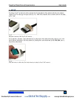
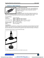
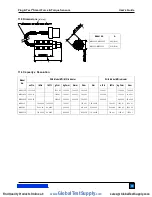
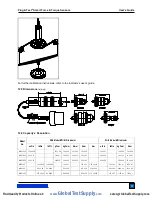
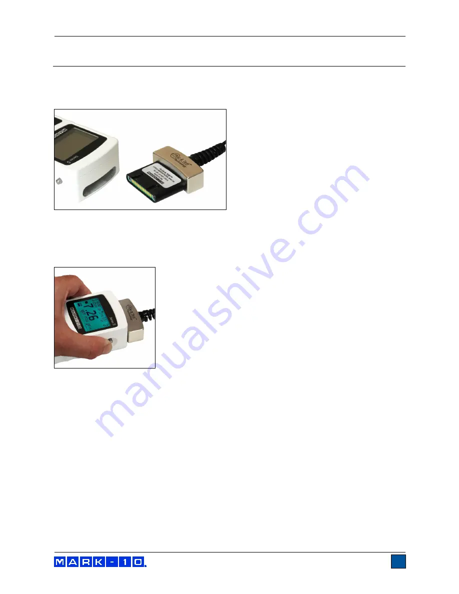
 connector must be inserted into the receptacle of the indicator with the side marked 

“Plug & Test

®

 Technology” facing up (see Fig. 3.1). When fully inserted, the connector will lock into place 

with a “click”.  


Fig. 3.1 

Appropriate orientation of the Plug & Test

®

 connector. 


To release the connector, press both buttons on either side of the indicator housing (see Fig. 3.2). Pull 

the connector completely out of the indicator by holding the curved aluminum section. 

DO


NOT

 pull on 

the cable or strain relief.  


Fig. 3.2 

Press both buttons on either side of the indicator housing to release the Plug & Test

®

 connector. 


www.

GlobalTestSupply

.com

Find Quality Products Online at:

sales@GlobalTestSupply.com

Summary of Contents for MR04-025M

Page 1: ...SMART FORCE AND TORQUE SENSORS User s Guide www GlobalTestSupply com Find Quality Products Online at sales GlobalTestSupply com...

Page 2: ...ective user s guides For additional information or answers to your questions please do not hesitate to contact us Our technical support and engineering teams are eager to assist you Before use each pe...

Page 3: ...sor accuracy to determine the total accuracy of the system Since sensors may be used with the M7I M5I or M3I indicators the accuracy of the indicator being used must be identified and taken into accou...

Page 4: ...ristics of the sample being tested before initiating a test A risk assessment should be carried out beforehand to ensure that all safety measures have been addressed and implemented 8 Typical material...

Page 5: ...ig 3 1 Appropriate orientation of the Plug Test connector To release the connector press both buttons on either side of the indicator housing see Fig 3 2 Pull the connector completely out of the indic...

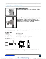
Page 6: ...4 3 Overview Tension and compression force may be applied to the surfaces with threaded holes Attachments may be threaded into these holes These holes also allow for mounting as required 4 4 Specific...

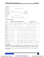
Page 7: ...50 x 0 5 7500 x 5 7 5 x 0 005 1500 x 2 750 x 1 7500 x 10 MR01 2000 2000 x 1 32000 x 20 1000 x 0 5 10000 x 5 10 x 0 005 2000 x 2 1000 x 1 10000 x 10 MR01 5000 5000 x 2 2500 x 1 25000 x 10 25 x 0 01 500...

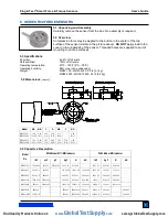
Page 8: ...32 8 1 0 05 1 3 0 39 9 9 1 0 25 4 0 83 21 1 MR02 5000 MR02 10000 1 50 38 1 0 43 10 9 0 07 1 8 0 62 15 8 1 25 31 8 0 25 6 4 1 08 27 4 5 5 Capacity x Resolution Model No With Model M7I M5I Indicator Wit...

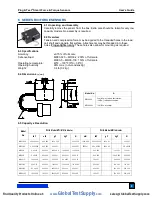
Page 9: ...Model M3I Indicator lbF ozF gF kgF N mN lbF gF kgF N MR03 025 0 25 x 0 0001 4 x 0 002 100 x 0 05 1 x 0 0005 1000 x 0 5 0 25 x 0 0002 100 x 0 1 1 x 0 001 MR03 05 0 5 x 0 0002 8 x 0 005 250 x 0 1 2 5 x...

Page 10: ...Indicator With Model M3I Indicator lbF ozF gF kgF N mN lbF gF kgF N MR04 025 0 25 x 0 0001 4 x 0 002 100 x 0 05 1 x 0 0005 1000 x 0 5 0 25 x 0 0002 100 x 0 1 1 x 0 001 MR04 05 0 5 x 0 0002 8 x 0 005 2...

Page 11: ...ments may be threaded into these holes Finger tighten only 8 3 Specifications Accuracy 0 15 of full scale Safe overload 150 of full scale Operating temperature 40 F 100 F 5 C 38 C Operating humidity 9...

Page 12: ...ead in the slot on the upper grip Begin to compress and release the handles slowly Tension force values will be displayed on the indicator After the test is complete remove any debris from the upper g...

Page 13: ...ne hand use an Allen wrench with the other hand to tighten the screw that joins the crosshead to the force sensor as shown at left Optionally cover the screw head with the included black plastic cap 1...

Page 14: ...FS05 20 20 x 0 01 320 x 0 2 10000 x 5 10 x 0 005 100 x 0 05 FS05 50 50 x 0 02 800 x 0 5 25000 x 10 25 x 0 01 250 x 0 1 FS05 100 100 x 0 05 1600 x 1 50000 x 20 50 x 0 02 500 x 0 2 FS05 200 200 x 0 1 3...

Page 15: ...ad MR50 10Z MR50 50Z 300 of full scale MR50 12 MR50 100 150 of full scale Chuck opening range MR50 10Z MR50 50Z 0 062 0 375 in 1 6 9 5 mm MR50 12 MR50 100 0 078 0 5 in 2 0 12 7 mm Operating temperatur...

Page 16: ...0 1 14 x 0 01 20 x 0 02 14 x 0 01 14 x 0 01 MR50 50Z 50 x 0 02 3600 x 2 36 x 0 02 350 x 0 2 35 x 0 02 50 x 0 05 36 x 0 05 35 x 0 05 MR50 12 12 x 0 005 1 x 0 0005 140 x 0 1 135 x 0 1 1 35 x 0 001 12 x...

Page 17: ...y models 12 3 Specifications Accuracy 0 2 of full scale Safe overload MR50 10Z MR50 50Z 300 of full scale MR50 12 MR50 100 150 of full scale Chuck opening range MR50 10Z MR50 50Z 0 062 0 375 in 1 6 9...

Page 18: ...x 0 01 7 x 0 005 7 x 0 005 MR51 20Z 20 x 0 01 1400 x 1 14 x 0 01 140 x 0 1 14 x 0 01 20 x 0 02 14 x 0 01 14 x 0 01 MR51 50Z 50 x 0 02 3600 x 2 36 x 0 02 350 x 0 2 35 x 0 02 50 x 0 05 36 x 0 05 35 x 0...

Page 19: ...sions in mm 13 5 Capacity x Resolution Model No With Model M7I M5I indicator With Model M3I indicator ozFin lbFin lbFft gFcm kgFmm Nmm Ncm Nm ozFin lbFin kgFmm Ncm MR52 10Z 10 x 0 005 700 x 0 5 7 x 0...

Page 20: ...ll scale Operating temperature 40 F 100 F 5 C 38 C Operating humidity 96 max non condensing Weight MR53 10Z MR53 50Z 2 2 lb 1 0 kg MR53 12 MR53 100 5 4 lb 2 5 kg 14 4 Dimensions in mm MR53 10Z MR53 50...

Page 21: ...002 230 x 0 2 220 x 0 2 2 x 0 002 20 x 0 02 230 x 0 2 220 x 0 2 MR55 50 50 x 0 05 4 x 0 005 580 x 0 5 570 x 0 5 5 7 x 0 005 50 x 0 05 580 x 0 5 570 x 0 5 MR55 100 100 x 0 1 8 x 0 01 1150 x 1 1150 x 1...

Page 22: ...lence in product design manufacturing and customer support In addition to our standard line of products we can provide modifications and custom designs for OEM applications Our engineering team is eag...

Reviews: