Series TT01 Digital Cap Torque Testers
User’s Guide
15
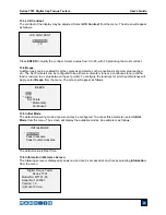
10.5.1 Auto Output Settings
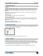
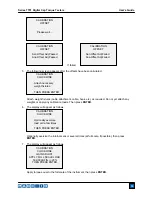
Select the output type. One, both, or no output types may be enabled. The display will appear as
follows:
10.5.2 Break Detection Settings
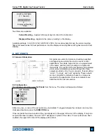
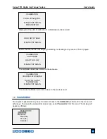
Set up the trigger for auto output and storage, and the delay to zero the display The display will
appear as follows:
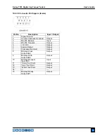
10.6 Analog Output
This output can be used for chart recorders, oscilloscopes, data acquisition systems, or any other
compatible devices with analog inputs. The output produces ±1 volt at full scale of the instrument. The
polarity of the signal is positive for clockwise and negative for counter-clockwise.
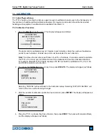
10.7 DATA Key Settings
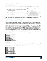
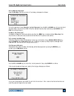
To configure the functions of the
DATA
key, select
DATA Key
from the menu. The display will appear as
follows:
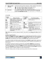
RS232/USB Output
Outputs data via the serial and USB ports
Mitutoyo Output
Outputs data via Mitutoyo (Digimatic) through the serial port
Memory Storage
Stores a reading to memory (refer to the
Memory
section for details)
Any combination of the above functions may be selected.
Trig. Threshold
Sets the percentage of full scale at which the break detection feature
becomes active. This threshold is provided to ignore torque peaks that can
occur during sample loading and unloading. Available settings:
5-50%
, in
5% increments.
Auto Zero Delay
Sets the time delay before the torque value is cleared from the screen.
Available settings:
1-60 sec
., in 5 sec. increments.
BREAK DETECTION
SETTINGS
Trig. Threshold
10 %
Auto Zero Delay
5 sec.
AUTO OUTPUT
SETTINGS
RS-232/USB Output
Mitutoyo Output
DATA KEY
*
RS232/USB Output
Mitutoyo Output
Memory Storage

