background image

Series TT01 Digital Cap Torque Testers 


User’s Guide 


21

 
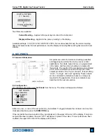
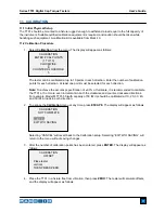
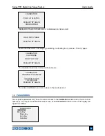
12.1 Calibration Password 

Select 

Calibration

 from the sub-menu. The display will appear as follows: 


To set the password, select 

Enabled

, then 

Set Password

. Use the 

UP

 and 

DOWN

 keys to increment and 

decrement the value, from 0 to 9999. When the desired value has been selected, press 

ENTER

, then 

ESC

 to exit the sub-menu. 

 
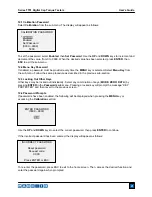
12.2 Menu Key Password 

If enabled, a password must be provided every time the 

MENU

 key is selected. Select 

Menu Key

 from 

the sub-menu. Follow the same procedure as described in the previous sub-section.  
 

12.3 Locking Out Other Keys 

Other keys may be locked out individually. Select any combination of keys (

MODE

ZERO

DATA

) by 

pressing 

ENTER

 in the 

Passwords

 sub-menu. Pressing a locked key will prompt the message “KEY 

PROTECTED” and then revert to the previous screen. 
 

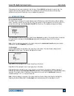
12.4 Password Prompts  

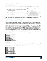
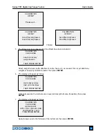
If passwords have been enabled, the following will be displayed when pressing the 

MENU

 key or 

accessing the 

Calibration

 section: 


Use the 

UP

 and 

DOWN

 keys to select the correct password, then press 

ENTER

 to continue. 

 
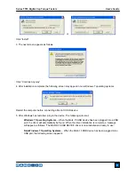
If the incorrect password has been entered, the display will appear as follows: 


To re-enter the password, press ESC to exit to the home screen. Then, access the desired function and 
enter the password again when prompted. 


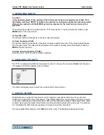
ENTER PASSWORD 

(0000 – 9999) 


5000


INCORRECT PASSWORD 


Reset password 

Request code: 

XXXX 


Press ENTER or ESC 

CALIBRATION PASSWORD 

 
 *  

Disabled 


    Enabled 
    Set Password 
    (0000 – 9999) 

5000 

Summary of Contents for MTT01-100

Page 1: ...Series TT01 DIGITAL CAP TORQUE TESTERS User s Guide ...

Page 2: ...peration instructions Dimensions and specifications are also provided For additional information or answers to your questions please do not hesitate to contact us Our technical support and engineering teams are eager to assist you Before use each person who is to use a Series TT01 digital cap torque tester should be fully trained in appropriate operation and safety procedures TABLE OF CONTENTS OVE...

Page 3: ...oad The following safety checks and procedures should be performed before and during operation 1 Never operate the tester if there is any visible damage to the AC adapter or the tester itself 2 Ensure that the tester is kept away from water or any other electrically conductive liquids at all times 3 The tester should be serviced by a trained technician only AC power must be disconnected and the te...

Page 4: ... in a five step process 1 When battery life is greater than 75 the following indicator is present 2 When battery life is between 50 and 75 the following indicator is present 3 When battery life is between 25 and 50 the following indicator is present 4 When battery life is less than 25 the following indicator is present 5 When battery life drops to approximately 2 the indicator from step 4 will be ...

Page 5: ...dually exert torque on the bottle cap by hand 3 1 Sample gripping methods Three different sample gripping methods are available as shown below Posts included Flat jaws optional Adjustable jaws optional 3 2 Proper alignment The center of the bottle cap should be positioned axially with respect to the center of the loading table Side loading or off center loading may produce erroneous readings and c...

Page 6: ...eases either to the right or left from the midpoint of the graph Increasing to the right indicates clockwise load increasing to the left indicates counter clockwise load If set points are enabled triangular markers are displayed for visual convenience This indicator reflects the actual load which may not correspond to the primary reading depends on operating mode The ZERO key does not reset the lo...

Page 7: ...ockwise and counter clockwise directions while configuring set points and other menu functions Note Measurement units are configured through the menu Refer to the Changing The Units section for details 4 3 Menu navigation basics Most of the tester s various functions and parameters are configured through the main menu To access the menu press MENU Use the UP and DOWN keys to scroll through the ite...

Page 8: ... ZERO will reset the value 5 3 Peak Counter clockwise PCCW Same as above but for counter clockwise readings 6 CHANGING THE UNITS The TT01 can display five different measurement units To change the unit select Units from the menu The display will list the available units as follows The tester will always power on with the unit selected in this sub menu 7 DIGITAL FILTERS Digital filters are provided...

Page 9: ...en indicators as well as through the three outputs provided on the 15 pin connector thus providing under in range and over signaling These outputs can be connected to indicators buzzers or relays as required for the application On screen indicators are described in the next sub section 8 2 Configuration To configure set points select Set Points from the menu The screen will appear as follows Eithe...

Page 10: ...s section for details Once data storage has been enabled the data record number 0000 will appear below the primary reading in the home screen The record number will increment each time DATA is pressed or the automatic data storage function is activated When memory is full the message MEMORY FULL will be flashed at the bottom of the display and a double audio tone will be sounded To view edit and o...

Page 11: ...ATS NOT SENT 9 6 Clear All Data Press ENTER to clear all data from the memory A prompt will be shown CLEAR ALL DATA Select Yes to clear all the data or No to return to the sub menu For output of data and or statistics RS 232 or USB output must be enabled Data formatting is CR LF following each value Units can be either included or excluded Output of data via the Mitutoyo output is possible however...

Page 12: ... 10 USB device 5 After Windows has restarted plug in the device The following will occur Windows 7 Operating Systems When the Mark 10 USB device has been plugged into a USB port the driver will automatically be found When the driver installation is complete a message will appear as follows The MARK 10 USB DEVICE driver is now installed and ready to use Non Windows 7 Operating Systems When the Mark...

Page 13: ...e Testers User s Guide 12 Select No not this time then click Next 6 The next screen appears as follows Select Install the software automatically Recommended then click Next 7 The next screen appears as follows Click Continue Anyway ...

Page 14: ...rs as follows Select either RS 232 or USB output Configure the baud rate and data format as required for the application Default values are as follows Baud Rate 9 600 Data Format Numeric units Auto Output Disabled Other communication settings are permanently set to the following Data Bits 8 Stop Bits 1 Parity None Individual data points may be transmitted by pressing DATA Continuous data may also ...

Page 15: ...arity The screen appears as follows 10 5 Break Detection Three functions can be triggered automatically upon bottle cap removal break detection defined as a 50 drop in load from the peak These functions automate the process of transmitting and saving multiple individual test data as well as zeroing the display If beeps are enabled an audible tone will sound when the automatic output automatic stor...

Page 16: ... key select DATA Key from the menu The display will appear as follows RS232 USB Output Outputs data via the serial and USB ports Mitutoyo Output Outputs data via Mitutoyo Digimatic through the serial port Memory Storage Stores a reading to memory refer to the Memory section for details Any combination of the above functions may be selected Trig Threshold Sets the percentage of full scale at which ...

Page 17: ... Overload Output 3 RS 232 Receive Input 4 RS 232 Transmit Output 5 12V DC Output 6 Analog Output Output 7 Clockwise Overload Output 8 Mitutoyo Clock Output Bit 2 Output 9 Mitutoyo Data Output Bit 0 Output 10 Mitutoyo Request Input Bit 3 Input 11 Under Set Point Output 12 Over Set Point Output 13 Within Set Point Output 14 15 Mitutoyo Ready Output Bit 1 Output ...

Page 18: ...full scale it is recommended to calibrate the TT01 at 5 or more even increments in both the clockwise and counter clockwise directions For example Model MTT01 50 with capacity of 50 lbFin should be calibrated at 10 20 30 40 and 50 lbFin loads in each direction 2 To escape the Calibration menu at any time press ESCAPE The display will appear as follows Selecting CANCEL will revert back to the Calib...

Page 19: ...eral times at full scale if possible then press ENTER 7 The display will appear as follows Apply torque equal to the full scale of the instrument then press ENTER CALIBRATION CLOCKWISE GAIN ADJUST APPLY FULL SCALE LOAD 50 000 LBFIN 20 THEN PRESS ENTER CALIBRATION CLOCKWISE Attach necessary weight fixtures THEN PRESS ENTER CALIBRATION CLOCKWISE Optionally exercise load cell a few times THEN PRESS E...

Page 20: ...er of data points selected 10 After all the clockwise calibration points have been completed the display will appear as follows Press ENTER 11 At the completion of the counter clockwise calibration the display will appear as follows To save the calibration information select SAVE EXIT To exit without saving the data select EXIT W O SAVING 12 Any errors are reported by the following screens CALIBRA...

Page 21: ...previous point 12 PASSWORDS Two separate passwords may be set to control access to the Calibration section and to the menu and other keys To access the passwords setup screen select Passwords from the menu The display will appear as follows PASSWORDS Calibration Menu Key Mode Key Zero Key Data Key CALIBRATION COUNTER CLOCKWISE LOAD TOO CLOSE TO PREVIOUS PLEASE TRY AGAIN LOAD NOT STABLE PLEASE TRY ...

Page 22: ...ut individually Select any combination of keys MODE ZERO DATA by pressing ENTER in the Passwords sub menu Pressing a locked key will prompt the message KEY PROTECTED and then revert to the previous screen 12 4 Password Prompts If passwords have been enabled the following will be displayed when pressing the MENU key or accessing the Calibration section Use the UP and DOWN keys to select the correct...

Page 23: ...the AC adapter is plugged in the tester will ignore the Automatic Shutoff setting and remain powered on until the POWER key is pressed 13 2 Backlight Several initial settings are available upon powering on the tester To access these settings select Backlight from the menu The display will appear as follows Select Off for the backlight to be off upon powering on the tester Select On for the backlig...

Page 24: ...ints To configure the functions for which audible tones will apply select Beeps from the menu The screen will appear as follows 13 5 Initial Mode The default measuring mode at power on may be configured To access this parameter select Initial Mode from the menu The screen will display the available modes An example is as follows The default value is Real Time 13 6 Information Welcome Screen The fo...

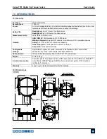
Page 25: ...en drain outputs one input Set points Three open drain lines Configurable settings Digital filters outputs set points automatic shutoff default units default mode passwords key tones audio alarms backlight calibration Safe overload 150 of full scale display shows OVER at 110 and above Weight 8 4 lb 3 8 kg Included accessories Set of four posts AC adapter battery USB cable resource CD USB driver ME...

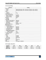
Page 26: ...ta Format Numeric units Mitutoyo BCD Output Disabled Break Detection Automatic Output RS 232 USB Output Disabled Mitutoyo Output Disabled Automatic Storage Disabled Automatic Zero Disabled Break Detection Settings Trigger Threshold 10 Auto Zero Delay 5 sec Automatic Shutoff Enabled Minutes 5 Beeps Keys Enabled Alerts Enabled Set Points Momentary LCD Contrast 10 Initial Mode Real Time Units lbFin P...

Page 27: ...Series TT01 Digital Cap Torque Testers User s Guide 26 NOTES ...

Page 28: ...tion to our standard line of products we can provide modifications and custom designs for OEM applications Our engineering team is eager to satisfy any special requirements Please contact us for further information or suggestions for improvement We make a measurable difference in force and torque measurement Mark 10 Corporation 11 Dixon Avenue Copiague NY 11726 USA 1 888 MARK TEN Tel 631 842 9200 ...

Reviews: