background image

Series TT02 Digital Torque Tool Testers 


User’s Guide 


14


11   DATA MEMORY AND STATISTICS  


Series TT02 testers have storage capacity of 1,000 data points. Readings may be stored, viewed, and 
output to an external device. Individual, or all, data points may be deleted. Statistics are calculated for the 
data presently in memory.  
 
Individual data points may be saved to memory by pressing the 

DATA

 key, or automatically via the 

Break 

Detection 

or

 First / Second Peak

 functions, whichever is enabled. Refer to the 

Break Detection 

and


First / Second Peak

 sections for details. Once data storage has been enabled, the data record number 

0000

 appears below the primary reading in the home screen. The record number will increment each time 

DATA

 is pressed or the automatic data storage function is activated. When memory is full the message 

“MEMORY FULL” will be flashed at the bottom of the display and a double audio tone will be sounded, if 
tones are enabled. 
 
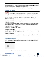
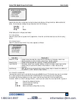
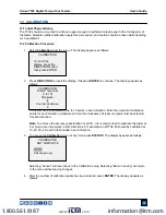
To view, edit, and output stored readings and statistics, select 

Memory

 from the menu. The screen 

appears as follows: 


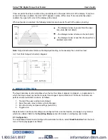
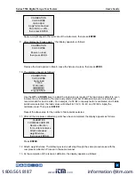
11.1 View Data  

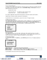
All the saved data points may be viewed. The record number is displayed, along with the corresponding 
value and presently set unit of measurement. Any readings may be deleted individually. To do so, scroll 
to the desired reading and press 

DELETE

. The letter “D” appears to the left of the record number, 

indicating that the tester is in 

Delete

 mode, as follows:  


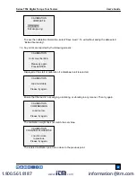
Press 

ENTER

 to delete the value. To exit 

Delete

 mode, press 

DELETE

 again. Any number of readings 

may be individually deleted, however, all readings may also be cleared simultaneously. Refer to the 

Clear 

All Data

 sub-section for details.  


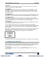
AUTO OUTPUT 

SETTINGS 


RS232/USB Output


    Mitutoyo Output 
    First Peak 
    Second Peak 

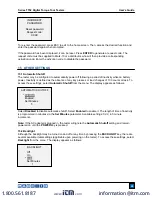
0001             2.458 lbFin 
0002             2.224 lbFin 
0003          2.446 lbFin 
0004             1.890 lbFin 

0005            2.098 lbFin 

0006          1.998 lbFin


0007             2.042 lbFin 

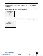
MEMORY 

View Data 

View Statistics 
Output Data 
Output Statistics 
Output Data & Stats 
Clear All Data 

www.

.com

information@itm.com

1.800.561.8187

Summary of Contents for MTT02-100

Page 1: ...Series TT02 TORQUE TOOL TESTERS User s Guide www com information itm com 1 800 561 8187...

Page 2: ...specifications are also provided For additional information or answers to your questions please do not hesitate to contact us Our technical support and engineering teams are eager to assist you Befor...

Page 3: ...afety checks and procedures should be performed before and during operation 1 Never operate the tester if there is any visible damage to the AC adapter or the tester itself 2 Ensure that the tester is...

Page 4: ...ess 1 When battery life is greater than 75 the following indicator is present 2 When battery life is between 50 and 75 the following indicator is present 3 When battery life is between 25 and 50 the f...

Page 5: ...the receptacle as shown below Gradually exert torque by hand until the desired status is achieved ex click slip etc 3 2 Using electric and pneumatic torque tools It is highly recommended to use a run...

Page 6: ...ng or off center loading may produce erroneous readings and can damage the instrument Note It is normal to detect a small amount of mechanical play in the receptacle 3 4 Mounting to a bench The tester...

Page 7: ...nit Abbreviations are as follows ozFin Ounce inch lbFin Pound inch kgFcm Kilogram centimeter Ncm Newton centimeter Nm Newton meter 5 Load bar Analog indicator to identify when an overload condition is...

Page 8: ...eading and peaks UP Navigates up through the menu and sub menus MENU Accesses the main menu ESCAPE Reverts one step backwards through the menu hierarchy MODE Toggles between measurement modes DOWN Nav...

Page 9: ...wise reading observed If the actual torque decreases from the peak value the peak will still be retained in the primary reading area of the display Pressing ZERO will reset the value 5 3 Peak Counter...

Page 10: ...e for best performance and the displayed reading filter at its highest value for best stability 8 SET POINTS 8 1 General Information Set points are useful for tolerance checking pass fail and triggeri...

Page 11: ...he current live load 8 2 1 Set Point Outputs Schematic Diagram 9 BREAK DETECTION The break detection function identifies when the tool has clicked slipped or stopped or applications in which the torqu...

Page 12: ...Output Auto Storage Automatically stores the peak reading to memory Auto Zero Automatically zeroes the display following data transmission and or storage A time delay may be configured in Break Detec...

Page 13: ...and zero functions have occurred In order for First Second Peak detection to be active the appropriate operating mode must be selected See the Operating Modes section for details The display appears...

Page 14: ...between 1 5 and in 5 increments between 5 90 Percentage Drop 1 Identifies the first peak via detection of a specified percentage drop from peak Threshold 2 Same as with Threshold 1 but refers to a pe...

Page 15: ...tone will be sounded if tones are enabled To view edit and output stored readings and statistics select Memory from the menu The screen appears as follows 11 1 View Data All the saved data points may...

Page 16: ...elect Yes to clear all the data or No to return to the sub menu For output of data and or statistics RS 232 or USB output must be enabled Data formatting is CR LF following each value Units can be eit...

Page 17: ...gative polarity counter clockwise values have positive polarity May be selected in addition to the Numeric Units Numeric Only selection Omit Polarity Both directions are formatted with positive polari...

Page 18: ...mitted by pressing DATA or by requesting it from the Mitutoyo communication device if available To enable Mitutoyo output select the desired format either with polarity or without polarity The display...

Page 19: ...r clockwise Greater than or equal to upper set point in clockwise Off On Off Between upper and lower set points Off Off On Greater than or equal to lower set point in counter clockwise On Off Off Uppe...

Page 20: ...clockwise At least one point must be selected for each direction Note To achieve the accuracy specification of 0 3 it is recommended to calibrate the tester at 5 or more even increments in both direc...

Page 21: ...apply any calibration loads Press ENTER 7 The display appears as follows Optionally exercise the torque sensor several times at full scale if possible then press ENTER 8 The display appears as follows...

Page 22: ...20 30 40 and 50 lbFin Apply the calibration load Then press ENTER Repeat the above step for the number of data points selected 11 After all the clockwise calibration points have been completed the di...

Page 23: ...is not swinging oscillating or vibrating in any manner Then try again The calibration weight does not match the set value The entered calibration point is too close to the previous point CALIBRATION...

Page 24: ...selected Select Menu Key from the sub menu Follow the same procedure as described in the previous sub section 14 3 Locking Out Other Keys Other keys may be locked out individually Select any combinati...

Page 25: ...access these settings select Automatic Shutoff from the menu The display appears as follows Select Disabled to disable automatic shutoff Select Enabled to enable it The length of time of inactivity i...

Page 26: ...CD Contrast The contrast of the display may be adjusted Select LCD Contrast from the menu The screen appears as follows Press ENTER to modify the contrast Select a value from 0 to 25 with 25 producing...

Page 27: ...ecting Restore Defaults from the menu The settings may be found in the Specifications section The display appears as follows 15 7 Information Welcome Screen The following screen is displayed at power...

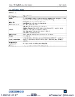
Page 28: ...e up to 115 200 baud Mitutoyo Digimatic Serial BCD suitable for all Mitutoyo SPC compatible devices Analog 1 VDC 0 25 of full scale at capacity General purpose Three open drain outputs one input Set p...

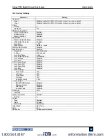
Page 29: ...Output Disabled Break Detection Disabled Threshold 5 of full scale Drop 50 of peak Auto Zero Delay 5 sec Auto Output Settings All disabled Auto Storage Disabled Auto Zero Disabled First Second Peak Di...

Page 30: ...m MTT02 12 192 x 0 1 12 x 0 005 14 x 0 01 135 x 0 1 1 35 x 0 001 MTT02 25 400 x 0 2 25 x 0 01 28 x 0 02 290 x 0 2 2 9 x 0 002 MTT02 50 800 x 0 5 50 x 0 02 58 x 0 05 570 x 0 5 5 7 x 0 005 MTT02 100 160...

Reviews: