background image

Series TT03 Digital Torque Gauges 


User’s Guide 


5

4   HOME SCREEN AND CONTROLS 


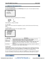
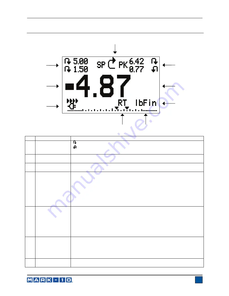
4.1 Home Screen 


No. Name 

Description 

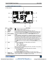
1 Measurement 

direction 
indicator 


– indicates clockwise direction  


– indicates counter-clockwise direction  

These indicators are used throughout the display and menu.   

2 Peaks 

The maximum measured clockwise and counter-clockwise readings. These 
readings are reset by pressing 

ZERO

 or by powering the gauge off and on. 

3 Primary 

reading 

The current displayed load reading. See 

Operating Modes

 section for 

details.  

4 Load 

bar 

Analog indicator to help identify when an overload condition is imminent. The 
bar increases either to the right or to the left from the midpoint of the graph. 
Increasing to the right indicates clockwise load, increasing to the left indicates 
counter-clockwise load. If set points are enabled, triangular markers are 
displayed for visual convenience. This indicator reflects the actual load, which 
may not correspond to the primary reading (depends on operating mode). 
The 

ZERO

 key does not reset the load bar. See 

Operating Modes

 section for 

details. 

5 Units 

The current measurement unit. Abbreviations are as follows: 
        lbFin – Pound-inch 
        ozFin – Ounce-inch 
        kgFmm – Kilogram-millimeter 
        Ncm – Newton-centimeter 

Note:

 not all sensor models display all the above units. Refer to the capacity / 

resolution table for details. 

6 Mode 

The current measurement mode. Abbreviations are as follows: 
       RT – Real Time  
       PCW – Peak Clockwise 
       PCCW – Peak Counter-clockwise 
See 

Operating Modes

 section for details about each of these modes 

Battery / AC 
adapter indicator 

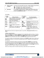
Either the AC adapter icon or battery power icon will be shown, depending on 
power conditions. Refer to the 

Power

 section for details.  

1

5

6

www.

GlobalTestSupply

.com

Find Quality Products Online at:

sales@GlobalTestSupply.com

Summary of Contents for MTT03-100

Page 1: ...Series TT03 DIGITAL TORQUE GAUGES User s Guide www GlobalTestSupply com Find Quality Products Online at sales GlobalTestSupply com ...

Page 2: ...d specifications are also provided For additional information or answers to your questions please do not hesitate to contact us Our technical support and engineering teams are eager to assist you Before use each person who is to use a Series TT03 digital torque gauge should be fully trained in appropriate operation and safety procedures TABLE OF CONTENTS OVERVIEW 2 POWER 3 SETUP 4 HOME SCREEN AND ...

Page 3: ...ation 1 Never operate the gauge if there is any visible damage to the AC adapter or the gauge itself 2 Ensure that the gauge is kept away from water or any other electrically conductive liquids at all times 3 The gauge should be serviced by a trained technician only AC power must be disconnected and the gauge must be powered off before the housing is opened 4 Always consider the characteristics of...

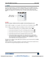
Page 4: ...75 the following indicator is present 2 When battery life is between 50 and 75 the following indicator is present 3 When battery life is between 25 and 50 the following indicator is present 4 When battery life is less than 25 the following indicator is present 5 When battery life drops to approximately 2 the indicator from step 4 will be flashing Several minutes after timing depends on usage and w...

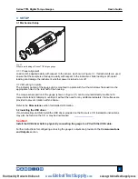
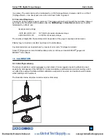
Page 5: ...the housing The torque sensor portion of the gauge shown in Figure 3 1 can be mounted directly to a Mark 10 torque test stand or tabletop mounting kit without the need for any additional adapters Flat surfaces are provided to prevent rotation within a fixture Refer to the Dimensions section for detailed information 3 2 Installing the USB driver If communicating via USB install the USB driver provi...

Page 6: ... If set points are enabled triangular markers are displayed for visual convenience This indicator reflects the actual load which may not correspond to the primary reading depends on operating mode The ZERO key does not reset the load bar See Operating Modes section for details 5 Units The current measurement unit Abbreviations are as follows lbFin Pound inch ozFin Ounce inch kgFmm Kilogram millime...

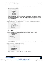
Page 7: ...ints and other menu functions Note Measurement units are configured through the menu Refer to Changing The Units section for details 4 3 Menu navigation basics Most of the gauge s various functions and parameters are configured through the main menu To access the menu press MENU Use the UP and DOWN keys to scroll through the items The current selection is denoted with clear text over a dark backgr...

Page 8: ...r clockwise PCCW Same as above but for counter clockwise readings 6 CHANGING THE UNITS The TT03 can display three different measurement units depending on the model To change the unit select Units from the menu The display will list the available units for example The gauge will always power on with the unit selected 7 DIGITAL FILTERS Digital filters are provided to help smooth out the readings in...

Page 9: ... or none of the set points may be enabled To toggle between the clockwise and counter clockwise directions press the DIRECTION key If two set points have been enabled they are displayed in the upper left corner of the display If only one set point has been enabled the word OFF appears in place of the value If no set points have been enabled the upper left corner of the display will be blank When s...

Page 10: ...rt Polarity Clockwise values have negative polarity counter clockwise values have positive polarity May be selected in addition to the Numeric Units Numeric Only selection Omit Polarity Both directions are formatted with positive polarity May be selected in addition to the Numeric Units Numeric Only selection 9 2 Data Output Communication with Series TT03 torque gauges is achieved through the micr...

Page 11: ...ndent of the gauge s capacity and resolution Polarity may be inverted or omitted as shown in the table above Any detected errors are reported back by means of error code 10 illegal command Series TT03 gauges can send individual data points or continuous data to MESUR TM gauge and MESURTM Lite software 10 CALIBRATION 10 1 Initial Physical Setup The sensor should be mounted vertically to a test stan...

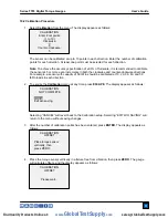
Page 12: ...lbFin loads in each direction 2 To escape the Calibration menu at any time press ESCAPE The display appears as follows Selecting CANCEL will revert back to the Calibration setup Selecting EXIT W O SAVING will return to the menu without saving changes 3 After the number of calibration points has been entered press ENTER The display appears as follows 4 Place the torque sensor vertically in a fixtur...

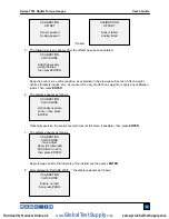
Page 13: ...ble then press ENTER 7 The display appears as follows Apply torque equal to the full scale of the instrument then press ENTER 8 After displaying PLEASE WAIT the display appears as follows CALIBRATION CLOCKWISE Gain adjust Apply full scale load 50 00 lbFin 20 then press ENTER CALIBRATION CLOCKWISE Ensure no load then press ZERO CALIBRATION CLOCKWISE Attach necessary weight fixtures then press ENTER...

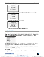
Page 14: ...llows Press ENTER 11 At the completion of the counter clockwise calibration the display appears as follows To save the calibration information select SAVE EXIT To exit without saving the data select EXIT W O SAVING 12 Any errors are reported by the following screens Displayed at the start of calibration if a disallowed unit is selected CALIBRATION Units must be Ncm Please try again Press ENTER CAL...

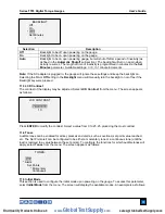
Page 15: ...bled to disable automatic shutoff Select Enabled to enable it The length of time of inactivity is programmed in minutes via the Set Minutes parameter Available settings 5 30 in 5 minute increments Note If the AC adapter is plugged in the gauge will ignore the Automatic Shutoff setting and remain powered on until the POWER key is pressed 11 2 Backlight Several initial settings are available upon po...

Page 16: ... may be adjusted Select LCD Contrast from the menu The screen appears as follows Press ENTER to modify the contrast Select a value from 0 to 25 25 producing the most contrast 11 4 Tones Audible tones can be enabled for all key presses and alerts such as overload set point value reached etc The Set Point alert can be configured to be either a momentary tone or a continuous tone until the load is re...

Page 17: ... The screen appears as follows 11 7 Information Welcome Screen The following screen is displayed at power up and can be accessed at any time by selecting Information from the menu RESTORE DEFAULT SETTINGS No Yes Digital Torque Gauge Series TT03 Model No MTT03 50 Serial No 1234567 Version 1 0 c Mark 10 Corp INITIAL MODE Real Time Peak Clockwise Peak Counter clockwise www GlobalTestSupply com Find Q...

Page 18: ...kgFmm Ncm depending on model USB output Individual data point output by pressing DATA button Configurable up to 115 200 baud Safe overload 150 of full scale display shows OVER at 110 and above Weight 1 8 lb 0 8 kg Included accessories Carrying case AC adapter battery USB cable resource CD USB driver MESUR TM Lite software MESURTM gauge DEMO software and user s guide NIST traceable certificate of c...

Page 19: ...Points Momentary Initial Mode Real Time Units Depends on gauge model 12 3 Capacity Resolution Model ozFin lbFin kgFmm Ncm MTT03 10Z 10 x 0 01 7 x 0 005 7 x 0 005 MTT03 20Z 20 x 0 02 14 x 0 01 14 x 0 01 MTT03 50Z 50 x 0 05 36 x 0 05 36 x 0 05 MTT03 12 192 x 0 2 12 x 0 01 135 x 0 1 MTT03 50 800 x 0 5 50 x 0 05 570 x 0 5 MTT03 100 1600 x 1 100 x 0 1 1150 x 1 12 4 Dimensions IN MM 3 90 99 1 2 53 64 3 ...

Page 20: ...nufacturing and customer support In addition to our standard line of products we can provide modifications and custom designs for OEM applications Our engineering team is eager to satisfy any special requirements Please contact us for further information or suggestions for improvement Force and torque measurement engineered better 32 1144 REV 1216 www GlobalTestSupply com Find Quality Products Onl...

Reviews: