background image

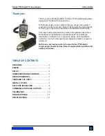
Series TT03 Digital Torque Gauges 


User’s Guide 


2


1   OVERVIEW  


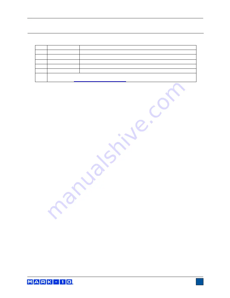
1.1  List of included items 


Qty. 

Part No. 

Description 

12-1049 

Carrying Case 

08-1022 

AC adapter body with US, EU, or UK prong 

08-1026 

Battery (inside the gauge) 

Certificate of calibration  

09-1165 

USB cable 

USB driver, MESUR

®

 Lite software, MESUR

®

gauge evaluation software, User’s Guide  

Download at: 

www.mark-10.com/resources


1.2 Safety / Proper Usage 


Caution! 

Note the torque 

gauge’s capacity before use and ensure that the capacity is not exceeded. 

Producing a torque 

greater than 150% of the gauge’s capacity can damage the internal sensor. An 

overload can occur whether the gauge is powered on or off. 

 
Typical materials able to be tested include many manufactured items, such as springs, electronic 
components, fasteners, caps, mechanical assemblies, and many others. Items that should not be used 
with the gauge include potentially flammable substances or products, items that can shatter in an unsafe 
manner, and any other components that can present an exceedingly hazardous situation when acted 
upon by a force. 
 
The following safety checks and procedures should be performed before and during operation: 
 

1.  Never operate the gauge if there is any visible damage to the AC adapter or the gauge itself.  


2.  Ensure that the gauge is kept away from water or any other electrically conductive liquids at all 

times. 


3.  The gauge should be serviced by a trained technician only. AC power must be disconnected and 

the gauge must be powered off before the housing is opened. 


4.  Always consider the characteristics of the sample being tested before initiating a test. A risk 

assessment should be carried out beforehand to ensure that all safety measures have been 
addressed and implemented. 


5.  Wear eye and face protection when testing, especially when testing brittle samples that have the 

potential to shatter under force. Be aware of the dangers posed by potential energy that can 
accumulate in the sample during testing. Extra bodily protection should be worn if a destructive 
failure of a test sample is possible. 
 

6.  In certain applications, such as the testing of brittle samples that can shatter, or other applications 

that could lead to a hazardous situation, it is strongly recommended that a machine guarding 
system be employed to protect the operator and others in the vicinity from shards or debris. 
 

7.  When the gauge is not in use, ensure that the power is turned off. 


Summary of Contents for MTT03-100E

Page 1: ...Series TT03 DIGITAL TORQUE GAUGES User s Guide...

Page 2: ...and operation instructions Dimensions and specifications are also provided For additional information or answers to your questions please do not hesitate to contact us Our technical support and engin...

Page 3: ...ures should be performed before and during operation 1 Never operate the gauge if there is any visible damage to the AC adapter or the gauge itself 2 Ensure that the gauge is kept away from water or a...

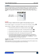
Page 4: ...cess 1 When battery life is greater than 75 the following indicator is present 2 When battery life is between 50 and 75 the following indicator is present 3 When battery life is between 25 and 50 the...

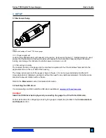
Page 5: ...our thumb screws fastened into the appropriate holes in the rear half of the housing The torque sensor portion of the gauge shown in Figure 3 1 can be mounted directly to a Mark 10 torque test stand o...

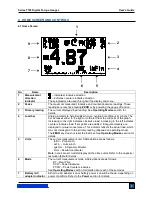
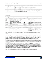
Page 6: ...the left indicates counter clockwise load If set points are enabled triangular markers are displayed for visual convenience This indicator reflects the actual load which may not correspond to the prim...

Page 7: ...kwise directions while configuring set points and other menu functions Note Measurement units are configured through the menu Refer to Changing The Units section for details 4 3 Menu navigation basics...

Page 8: ...ZERO will reset the value 5 3 Peak Counter clockwise PCCW Same as above but for counter clockwise readings 6 CHANGING THE UNITS The TT03 can display three different measurement units depending on the...

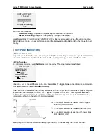
Page 9: ...screen appears as follows Either one two or none of the set points may be enabled To toggle between the clockwise and counter clockwise directions press the DIRECTION key If two set points have been...

Page 10: ...he value only Polarity same as above Invert Polarity Clockwise values have negative polarity counter clockwise values have positive polarity May be selected in addition to the Numeric Units Numeric On...

Page 11: ...of digits after the decimal point is dependent of the gauge s capacity and resolution Polarity may be inverted or omitted as shown in the table above Any detected errors are reported back by means of...

Page 12: ...ould be calibrated at 10 20 30 40 and 50 lbFin loads in each direction 2 To escape the Calibration menu at any time press ESCAPE The display appears as follows Selecting CANCEL will revert back to the...

Page 13: ...nsor several times at full scale if possible then press ENTER 7 The display appears as follows Apply torque equal to the full scale of the instrument then press ENTER 8 After displaying PLEASE WAIT th...

Page 14: ...been completed the display appears as follows Press ENTER 11 At the completion of the counter clockwise calibration the display appears as follows To save the calibration information select SAVE EXIT...

Page 15: ...he display appears as follows Select Disabled to disable automatic shutoff Select Enabled to enable it The length of time of inactivity is programmed in minutes via the Set Minutes parameter Available...

Page 16: ...LCD Contrast The contrast of the display may be adjusted Select LCD Contrast from the menu The screen appears as follows Press ENTER to modify the contrast Select a value from 0 to 25 25 producing th...

Page 17: ...ay be found in the Specifications section The screen appears as follows 11 7 Information Welcome Screen The following screen is displayed at power up and can be accessed at any time by selecting Infor...

Page 18: ...24 hours of continuous use Measurement units lbFin ozFin kgFmm Ncm depending on model USB output Individual data point output by pressing DATA button Configurable up to 115 200 baud Safe overload 150...

Page 19: ...isabled Baud Rate 9 600 Data Format Numeric units Automatic Shutoff Enabled Minutes 5 Tones Keys Enabled Alerts Enabled Set Points Momentary Initial Mode Real Time Units Depends on gauge model 12 3 Ca...

Page 20: ...ition to our standard line of products we can provide modifications and custom designs for OEM applications Our engineering team is eager to satisfy any special requirements Please contact us for furt...

Reviews: