Series TT03 Digital Torque Gauges
User’s Guide
4
3 SETUP
3.1 Mechanical Setup
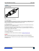
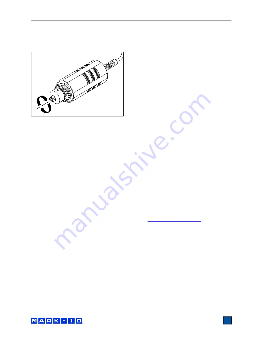
Fig. 3.1
Proper axial loading of Series TT03 torque gauge.
3.1.1 Proper alignment
Load must be applied axially with respect to the sensor, as shown in Figure 3.1. If attachments are used,
ensure that the sample is acted upon axially with respect to the instrument. Side loading or off-center
loading can damage the instrument, whether power is turned on or off.
3.1.2 Mounting to a plate
The indicator portion of the gauge can be mounted to a plate with four thumb screws fastened into the
appropriate holes in the rear half of the housing.
The torque sensor portion of the gauge (shown in Figure 3.1) can be mounted directly to a Mark-10
torque test stand or tabletop mounting kit without the need for any additional adapters. Flat surfaces are
provided to prevent rotation within a fixture.
Refer to the
Dimensions
section for detailed information.
3.2 Installing the USB driver
If communicating via USB, install the USB driver available at:
Caution!
Install the USB driver before physically connecting the gauge to a PC with the USB cable.
Further instructions for configuring and using the gauge’s outputs are provided in the
Communications
and Outputs
section.

