background image

Series TSTM-DC Test Stands    


   User’s Guide


21


Command

Description

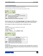
Test Stand status 

CW 

Test stand moving CW

CCW 

Test stand moving CCW

Test stand stopped

Operating mode 

Cycle mode

Limit mode

Manual mode

Limit switch status 

CWL 

Test stand at CW limit

CCWL 

Test stand at CCW limit

 
While in PC control, if any functions are changed on the control panel, these settings will be ignored, 
except if Auto Return or Cycling are turned on. If so, PC control will be turned off automatically. 


7  MAINTENANCE AND SERVICE 


The TSTM-DC should be operated in a dry and clean area. Under these circumstances only a few 
periodic maintenance operations are required: 
 

7.1 Check for loosened grips and attachments – daily 

Check to ensure that the grips attached to the torque sensor and torque plate are firmly secured. 
Looseness could result in a potentially hazardous situation. 
  

7.2 Check for loosened components – once per month 

1.  Remove the test sample from the test stand.


2.  Attempt to loosen subcomponents of the test stand (ex. fasteners, brackets, etc). All components 

should be firmly attached. If any looseness is detected, stop using the test stand and contact 
Mark-10 or a distributor for instructions.


8   TROUBLESHOOTING  


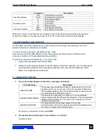
1.  The control panel displays several error messages, as follows: 


Error Message 

Description

CHECK GAUGE 

The torque sensor/indicator is either (1) powered off, (2) not in its 
operating mode (i.e. in a menu), or (3) not connected to the stand. 
This message appears only if overload protection is turned on and 
one of the above conditions is present. 

GAUGE COMM ERROR 

The test stand is attempting to rotate, but it cannot establish 
communication with the torque sensor/indicator. The communication 
settings in the indicator are not correct or the indicator is not in its 
normal operating mode. 

GAUGE OVERLOAD 

The programmed overload percentage of the


torque 

sensor/indicator’s full scale has been reached. Immediately reduce 
the torque or adjust the overload settings. 


To clear any of the above errors, press 

STOP

.  


2.  The test stand will rotate only in one direction, or not at all.  

 
Possible causes: 


Summary of Contents for TSTM-DC

Page 1: ...Series TSTM DC Motorized Torque Test Stands User s Guide...

Page 2: ...p safety and operation instructions Dimensions and specifications are also provided For additional information or answers to your questions please do not hesitate to contact us Our technical support a...

Page 3: ...g the pair of screws at each end Install the indicator mounting kit on the column For the vertical models install the base with four 5 16 18 x 1 screws and the top cap with four ribbed push in rivets...

Page 4: ...the control panel can be mounted at any angle although extra care should be taken during installation and operation IMPORTANT Do not fasten any screws more than 0 25 in 6 mm into the base of the cont...

Page 5: ...lows for PC control if appropriate functions are enabled Plug one end of the 09 1056 serial cable into this connector and the other end into a serial connector on a computer or USB converter 4 Power P...

Page 6: ...ances or products items that can shatter in an unsafe manner and any other components that can present an exceedingly hazardous situation when acted upon by torque When using a grip ensure that it sec...

Page 7: ...worn if a destructive failure of a test sample is possible 3 Keep away from moving parts of the test stand Loose articles of clothing should not be worn Long hair should be covered to avoid a hazardo...

Page 8: ...cycles password editing and other functions 2 OPERATING MODE This is the operating mode in which testing sequences can be started and stopped SOFT KEYS Functions are determined by the corresponding t...

Page 9: ...of settings before saving 4 1 Speed Independent speeds can be set for both directions of movement Default setting 10 RPM 60 s Available settings TSTM DC TSTMH DC 0 01 15 RPM 0 05 90 s TSTM DC 2 TSTMH...

Page 10: ...mpletions in the M7I whichever occurs first at the specified speed stopping for the specified amount of dwell time and returning to the other limit at the specified speed Default setting 00000 off Ava...

Page 11: ...he next number will be 9999 9 and continue decrementing ENTR Returns to the Test Function Setup menu ESC Exits the function without saving changes 4 5 CW and CCW travel limits CW L and CCW L This sett...

Page 12: ...D and CCW OVERLOAD This setting corresponds to the percentage of full scale at which torque plate rotational travel stops For example a setting of 80 for a 100 lbFin capacity torque sensor would stop...

Page 13: ...400 57600 115200 Label Description or Cycles through the available settings ENTR Returns to the Function Setup menu ESC Exits the function without saving changes 4 9 Stop bits and parity STOP PAR This...

Page 14: ...tton has been pressed and held Subsequently pressing STOP will stop torque plate motion 2 Momentary The torque plate will rotate only if the button is held down Releasing the button will stop movement...

Page 15: ...indicates that the password is disabled and that the user can freely enter the Test Function Setup menu Default setting 0000 off Available settings 0000 9999 Label Description or Increases or decreas...

Page 16: ...ses and moves at maximum speed to the other limit whichever occurs first 3 Cycling Mode Test stand cycles between limits at the selected speed and pauses at each limit for a selected period of time 4...

Page 17: ...in motion an LED indicator on the button pushed will be illuminated The KEYS setting controls how test stand movement responds to the push of either of the directional buttons The three settings are 1...

Page 18: ...the set speed to whichever limit it encounters first and stops Then it returns at maximum speed to the opposite limit whichever occurs first and stops Press either directional button to initiate an Au...

Page 19: ...equence Press either directional button to resume Once the sequence has been completed the screen will revert to the number of cycles programmed originally To begin another cycle test press either dir...

Page 20: ...quired g 000007 5 7 5 Deg g000010 7 10 7 Deg h Set CW travel limit Revolutions format h XXXX XX Negative sign if applicable four leading zeroes and two decimal places required h 0010 55 10 55 Turns h0...

Page 21: ...the test stand 2 Attempt to loosen subcomponents of the test stand ex fasteners brackets etc All components should be firmly attached If any looseness is detected stop using the test stand and contact...

Page 22: ...ed variation with load 0 Stepper motor driven Speed accuracy 0 2 of setting Rotational travel accuracy 0 7 0 02 rev Rotational travel repeatability 0 1 0 01 rev Rotational travel resolution 0 1 0 01 r...

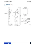
Page 23: ...Series TSTM DC Test Stands User s Guide 23 10 DIMENSIONS in mm TSTM DC...

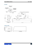
Page 24: ...Series TSTM DC Test Stands User s Guide 24 TSTMH DC CONTROL PANEL...

Page 25: ...Series TSTM DC Test Stands User s Guide 25 NOTES...

Page 26: ...pport In addition to our standard line of products we can provide modifications and custom designs for OEM applications Our engineering team is eager to satisfy any special requirements Please contact...

Reviews: